G424F(FE) Service Manual Chapter 3. Engine Mechanical System 46
Removal
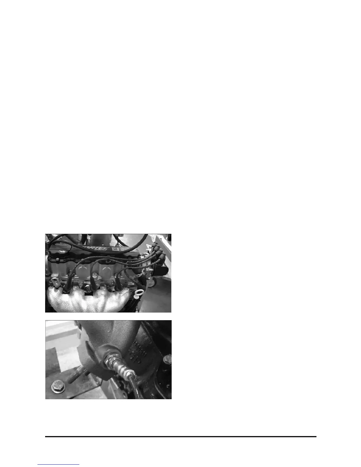
Remove or disconnect
1. Spark plug cable terminals;
2. Exhaust manifold heat shield and remove dipstick
tube (to allow removal of #3 plug wire).
3. Oxygen sensor (O2) electric connection.
4. Adapter-Manifold
5. Remove attaching bolts of adapter with 6 mm hex
– bit socket.
6. Exhaust manifold-to-cylinder head attaching nuts,
with a 13-mm socket wrench, extension and
handle.
7. Exhaust manifold and gasket.
Clean
• Exhaust manifold and cylinder head gasket
residues, taking care not to scratch the gasket
mating surfaces.
Installation
Install or connect
1. New gasket between the exhaust manifold and
cylinder head.
2. Exhaust manifold and attaching nuts, without
tightening.
3. With a 13-mm socket wrench, extension and
torque wrench; tighten.
Tighten
• Nuts: 18 – 22 N·m (13 – 16 lb·ft.)
4. New gasket between the exhaust manifold and
adapter.
5. Exhaust adapter and attaching bolts Without
tightening.
6. With a 6mm hex-bit socket, extension and torque
wrench; tighten.
• Tighten : 25 ~ 30N.m
7. Oxygen sensor to the adapter, with 22mm torque
spanner tighten.
8. Washer and plug to the exhaust manifold, with
19mm socket wrench, extension and Torque
wrench; tighten.
• Torque : 60 ~ 70N.m
9. Heat shield and attaching bolts, without tightening.
10. With a T30 socket wrench and torque
Wrench; tighten.
• Tighten: 6 ~ 8N.m
11.Spark plug cables, observing their sequence.