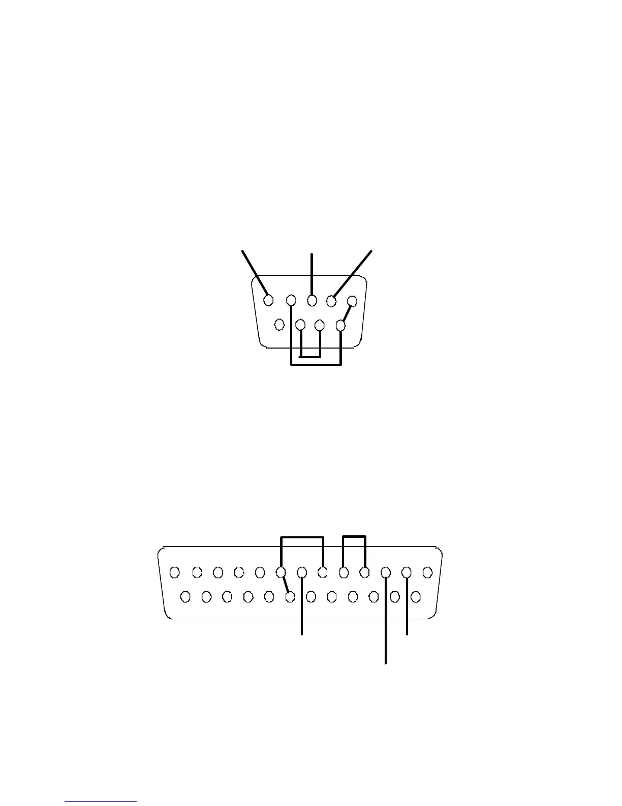
RS232 NULL MODEM CABLE WITH DB9 CONNECTOR
The diagram shown below should be used to wire a DB9 connector to port 1 (duplex) for
RS232 operation. The jumpers shown between pins 1,4,6 and 7,8 are necessary in most
cases to provide the proper control signals to the computer or other equipment that the
DB9 connector will be plugged into. Consult the manual for the equipment you are using
for more information on the connections it requires. See Section 8 for more information
about port 1.
RS232 NULL MODEM CABLE WITH DB25 CONNECTOR
The diagram shown below should be used to wire a DB25 connector to port 1 (duplex) for
RS232 operation. As with the DB9 connector, the jumpers shown are usually necessary for
proper operation. Consult the manual for the equipment to which you are connecting for
more information on the necessary connections. See Section 8 for more information about
port 1.
Section 12 Connections
79
TXD (Red)RXD (Wht)
Signal
Ground (Blk)
1
2
345
6789
Signal
Ground (Blk)
RXD (Wht)
TXD (Red)
1
2
3456
89
1011
12
13
15
1416
17
18
192021
22
23
2425