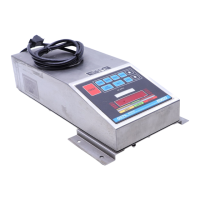
REMOTE ZERO SWITCH
J3-Position
J3-1 Requires Molex type pins and connector
J3-2 Requires a Normally open switch closure
LOAD CELL CONNECTIONS
TB1-Position FUNCTION COLOR CODE
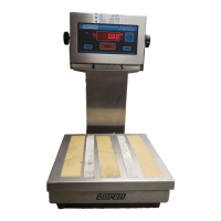
Doran Platforms
COLOR CODE
Redi-Weigh
Floor Bases
TB1-1 Chassis Ground Bare Braided
TB1-2 + Signal Red White
TB1-3 - Signal White Red
TB1-4 + Excitation Green Green
TB1-5 - Excitation Black Black
TB1-6 + Sense Blue N/A
TB1-7 - Sense Brown N/A
TB1-8 Chassis Ground
To enable sense capability, cut traces BC4 and BC5. Make sure that if these traces are
cut, that either the sense leads are connected to the load cell or a jumper is placed
between +excitation and +sense then a jumper between - excitation and - sense.
POWER SUPPLY CONNECTIONS
J6-Position Function
J6-1 Not Connected
J6-2 Neutral, 115VAC (230VAC)
J6-3 Not Connected
J6-4 Hot, 115VAC (230VAC)
Note: The ground wire from the power cord should be connected to the ground stud which
is located directly next to the power cord watertight fitting.
For 230VAC Setup:
1. Cut traces "CUT1" and "CUT2"
2. Place a jumper at "JU1"
3. Replace fuse, F1, with proper fuse
Section 12 Connections
80