10
E7900 Series
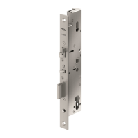
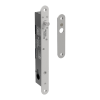
3.3 Install the Mortise
IMPORTANT
If using the installation jig to pre-
pare the door, refer to the instruc-
tions provided with the jig, then
proceed with step 6 below.
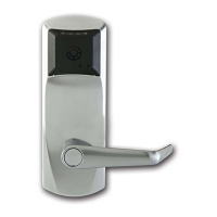
1. Mark the handle ( ) height
on the edge of the door, as de-
termined directly from the strike.
For ASM, the axis of rotation of
the handle is level with the
bottom lip of the strike.
For cylindrical models, see B2
in Appendix B
2. Align the template along the ver-
tical center line of the mortise
(CL) at the desired handle
height, and tape it to the door.
Mark all holes and cutouts for
the mortise in the edge of the
door and remove the template.
2
5
4
3
H1
3. Locate the two sets of vertical fold lines on the template
allowing you to adjust the positioning of the template de-
pending on the bevel of the door.
If the door has no bevel, fold the template along the solid
lines. Align the fold with the edge of the door and mark the
holes for the lock. Repeat on the other side of the door.
If the door has a 3º bevel, fold and align the dashed line
marked “H" on the template with the higher-beveled edge
of the door and mark the lock holes on that side of the door.
Repeat on the side with the lower-beveled edge using the
dashed line marked “L". Remove the template.
4. Prepare the cut-outs for the mortise in the edge of the
door using a mortising machine, router and chisel (for di-
mensions, refer to template).
Ensure clearance is provided for moving latch parts as indi-
cated on the template.
RH/LHR (ASM shown) LH/RHR
5. Drill the holes in the sides of the door (for dimensions,
refer to template).
IMPORTANT
Drill from both sides of the door to prevent unsightly dam-
age
6. For ASM only, check the bevel of the mortise. If adjust-
ment is required, loosen bevel screws (D1) and adjust
mortise front plate angle to match the bevel of the door.
Re-tighten screws.
Install the mortise with 2 screws (J). Use wood screws for
wood doors and machined screws for steel doors.
Install mortise faceplate (D2) with the two 8-32 x 1/4"
screws provided.
Logo
D2
J
D1
D1
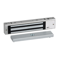
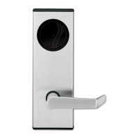
3 Installation of Standard ASM Models
ASM
Strike
Door
(CL)
KD10114-E-1122