5 Programming and Software Setup - M-Unit
32 E7900 Series
Ping Network
5.8.5.
1. From the main screen, select Wireless by pressing the
middle arrow button below the screen.
2. Choose Ping Network by either selecting the
corresponding number on the number pad or by
scrolling through the options with the up and down
arrow buttons and selecting with the ENTER button.
3. Select Ping by pressing the left-most arrow button
below the screen. After a few seconds, the M-Unit will
identify the closest ZigBee network. If the M-Unit fails
to find a ZigBee network, try the test again by pressing
the left-most arrow button below the screen to select
Ping. If multiple attempts fail, troubleshoot the
Gateway hosting the ZigBee service.
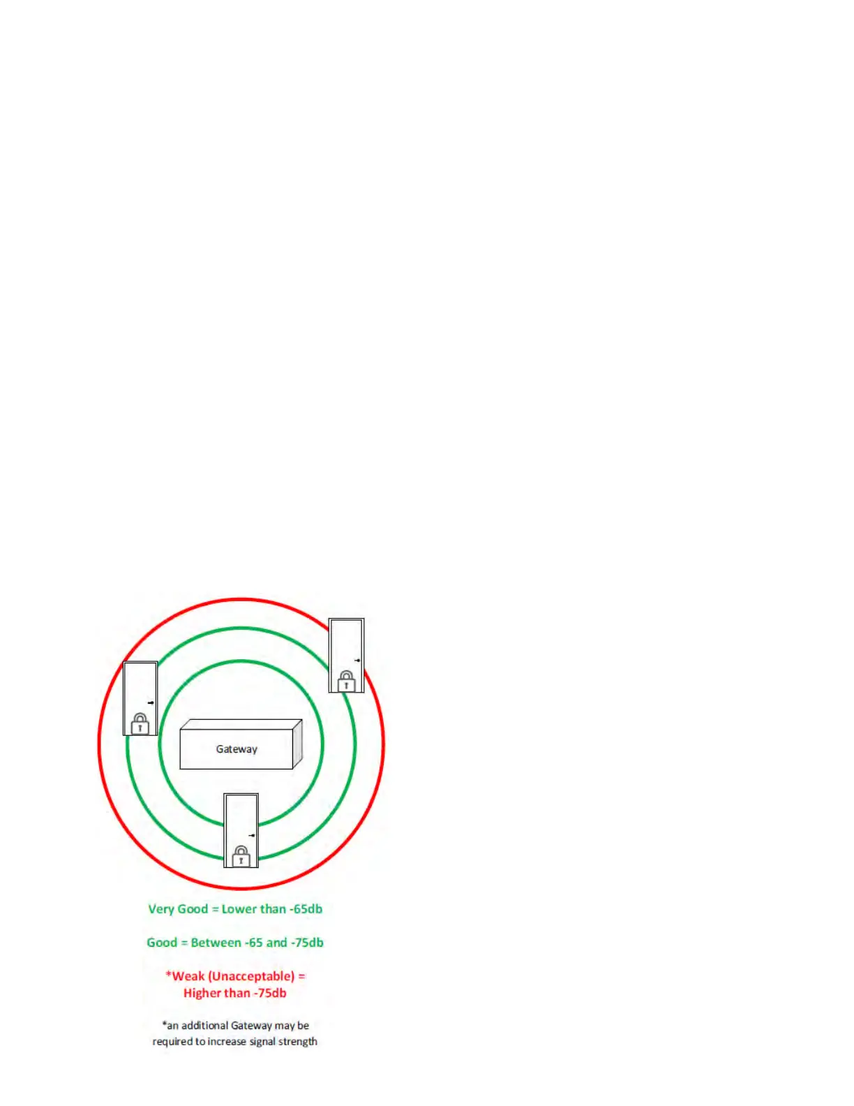
4. A bar will illuminate on screen identifying the ZigBee
signal strength as either Very Good, Good or
Unacceptable. View the illustration below for varying
signal strength indicators. It is recommended to stay
within the Green range to limit service interruptions to
the lock. If the range is within the Red area, either
move the Gateway closer to the lock, or add an
additional Gateway to extend the range. Once an
acceptable range is decided, install the E-Plex lock at
the desired location.
To determine correct lock placement in comparison to
Gateway location, the M-Unit can ping a ZigBee network
to determine signal strength from the Gateway. Follow
these steps to ping a ZigBee network:
1. From the main screen, select Door by pressing the
left-most arrow button below the screen.
2. Choose Diagnostic by either selecting the
corresponding number on the number pad or by
scrolling through the options with the up and down
arrows and selecting with the ENTER button.
3. Choose 79xx Series by either selecting the
corresponding number on the number pad or by
scrolling through the options with the up and down
arrows and selecting with the ENTER button.
4. The screen will display Put Lock into Communications
Mode (see section 5.7.3 of this document)
5. Attach the Programming Unit Adaptor onto the lock
and attach the other end into the serial port of the
M-Unit.
6. Select OK by pressing the right-most arrow button
below the screen. Initializing Comms is displayed on
screen while the M-Unit diagnoses the lock.
7. Upon completion, the following information is
displayed:
8. Select OK by pressing the right-most arrow button
below the screen and return to the main menu.
Diagnosing an E-Plex 7900 Lock
5.8.6.
a. Lock Model – Displays the E-Plex lock model
b. Firmware Version – Shows the current
firmware version of the lock
c. Battery Voltage – Displays the lock’s battery
voltage
d. HW Voltage – Shows the lock’s hardware
voltage
e. Lock Function – Displays the lock function
between Entry, Residence and Privacy
f. BLE Version – Shows if the lock is BLE-enabled
g. Lock Date – Displays the current date and time
of the lock pulled from the MUnit when the
door is programmed
KD10114-E-1122