E7900 Series
11
3 Installation of Standard ASM Models
3.4 Install the Outside Housing and Inside Trim Assembly
Without Key Override
A- For Mortise
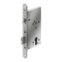
1. Insert the slotted end of the square spindle (G) into the
outside lever hub at an angle of 45 degrees, until it locks.
Then insert the thumbturn spindle (F) in the upper hub of
the outside housing and align the marks as shown in the
diagram. (The spindle G can be removed by pulling on it if
orientated incorrectly).
For Spindle F, insert as indicated above. Washer is to be
positioned against the back of the outside housing (B)
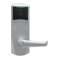
2. Install the gasket (N) (if required) on the outside housing
prior to assembly, aligning the notch in the gasket with the
batt
ery compartment. See page 3 for gasket information.
If installing the lock with mortise outdoors, order the proper
Gasket (See page 3).
For doors more than 2 1/2" thick, order the appropriate
hardware bag to receive the correct length of spindles and
mounting screws. (See page 3)
3. Place the outside housing on the door so that the spindles
engage the hubs on the mortise. For all locks with cables,
insert cables W when applicable in Hole (H1) on the door.
WW
H1
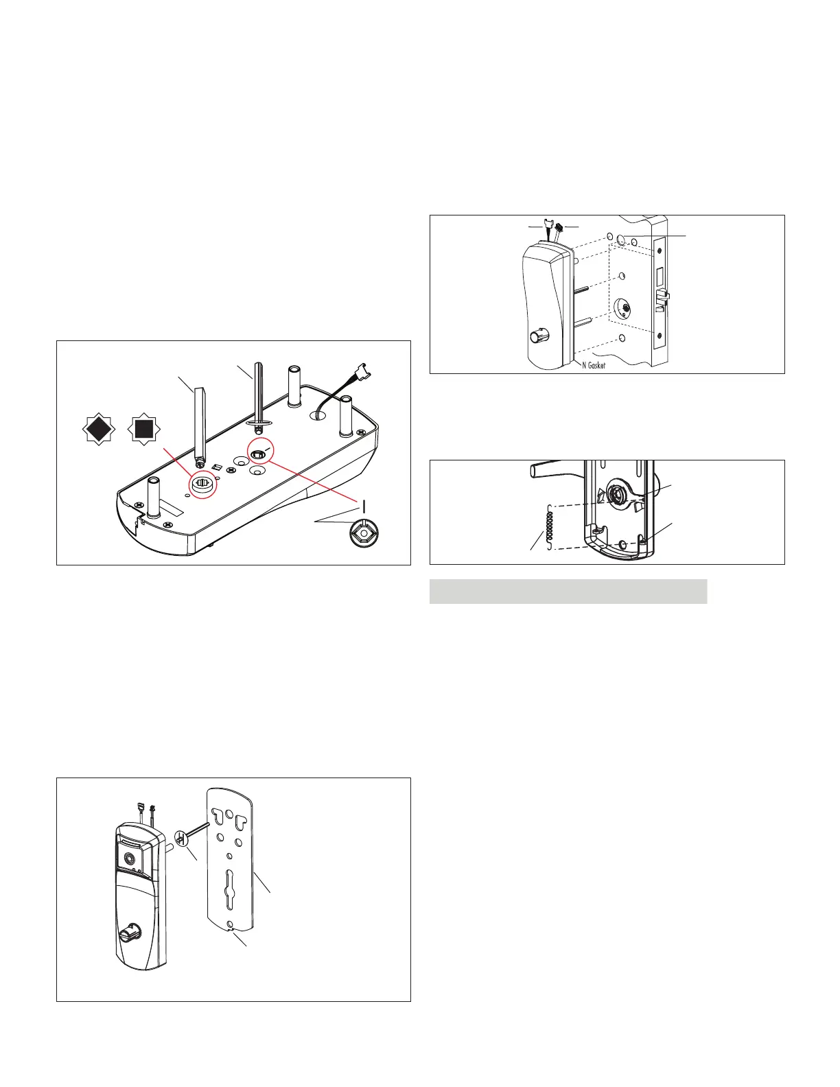
4. On the inside trim assembly turn the lever to the correct
horizontal rest position for the handing of the door. In-
stall the tension spring (L) between the handle (H) and
the post (P).
U
P
L
For ASM Office and ASM Store-room models, refer to
Appendix A.2 and A.3 at this point.
5. Put the thumbturn (T) in a vertical position. Place 3 spac-
ers (S) on the door (for recent models only) and place
the inside trim assembly on the
door so that the upper
and lower spindles (F1/F2) and (G) engage the thumb-
turn and the inside lever. Fasten to the outside housing
using the three 1/8" hex drive mounting screws (I ). Install
the screws without tightening. Verify the inside lever and
thumbturn operates smoothly. If not move the inside
and outside housings slightly. Then tighten the screws.
Square Spindle Position
correct incorrect
G
F
Align marks
Plate and/or Gasket
Notch
F
KD10114-E-1122