12
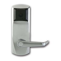
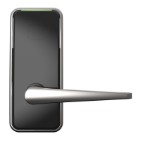
E7900 Series
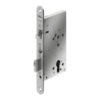
For all models, connect outside housing cables with cor-
responding inside trim cables when applicable. Put excess
cables in hole (H1) when installing the inside trim.
W
W
H1
V
F
G
V
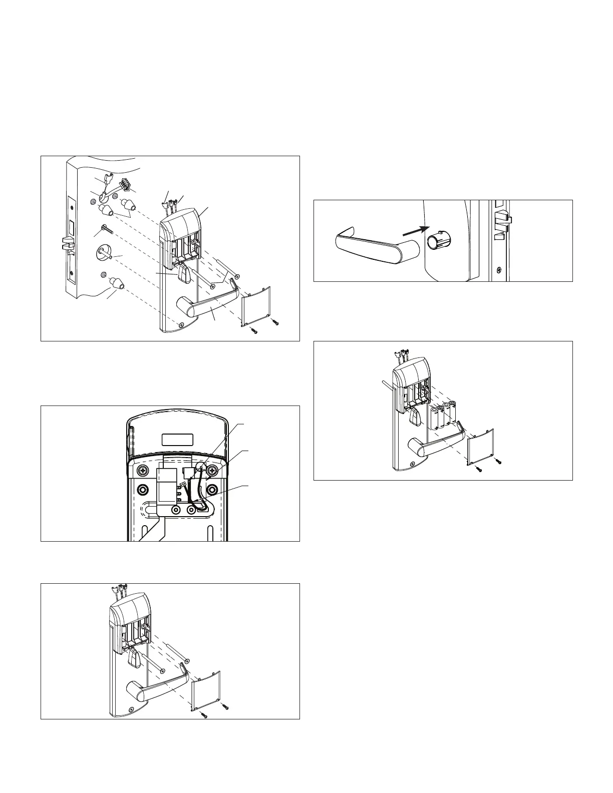
For 79T with ble or E, connect cables with corresponding
connectors together (route the w6 in the switch holder as
shown in the next figure) and put the excess cables in the
area a when installing the inside trim.
A
W6
W4
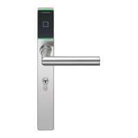
For E7900 series, the battery enclosure cover must be
removed to install the mounting screws.
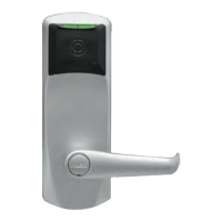
6. Assemble the lever on the outside housing, in the
horizontal rest position appropriate to the hand-
ing of the door. Simply push the lever onto the tube
until it clicks in place. If more force is required, use a
rubber mallet. Test the attachment
of the handle by pull-
ing smartly on it.
7. For E7900, after the mounting screws have been instal-
led, insert batteries and refasten the battery
enclosure cover into place.
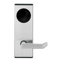
3 Installation of Standard ASM Models
W
W
Y
T
I
E3
KD10114-E-1122
 Loading...