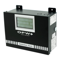
1. Choose a location for the first OM4 Output Module within the six-
foot reach of the supplied DIN cable (OPW Fuel Management
Systems part number 20-1582).
NOTE: If installing a second OM4 Output Module, place it within four
feet of the first. Longer distances may cause improper operation. Allow
room at the bottom of the module(s) for conduit.
2. Remove the cover/module assembly from each OM4 box.
3. Mount each box to a wall using the box’s four mounting holes.
NOTE: If installing two (2) OM4 Output Module boxes, run dedicated
steel conduit between them for the additional power and
communication wiring.
NOTE: Run steel conduit for the relays to a knock-out on the bottom
of EACH box. When installing two OM4 Output Module boxes, DO
NOT route the relay wiring through box to the other! Doing so may
cause improper operation Pull all relay wiring through the conduit(s).
4. See the figure at top-right. Remove the metal plug from the right
side of the Controller to expose the DIN connector inside.
5. See the figure at bottom-right. Attach the DIN connector on the
20-1582 cable to the controller
6. Route the other end of the 20-1582 cable through the supplied
bushing/strain relief.
7. Insert the bushing into a knockout hole in the first OM4 Output
Module box. Secure the busing to the box.

 Loading...