CONTACT US AT www.DRpower.com
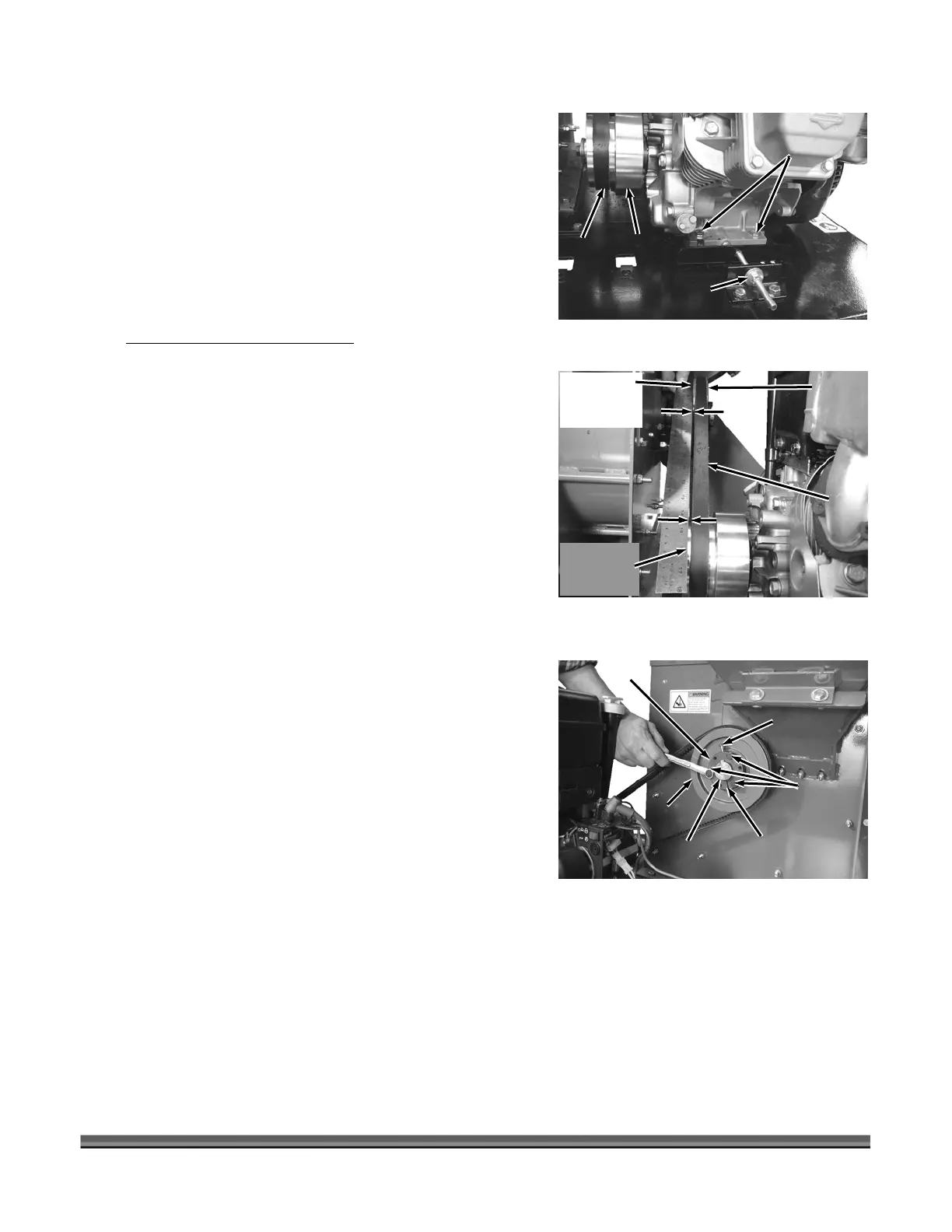
4. Loosen the four Engine Bolts (two o nd
two on the right side) using two 1/2" Wrenches n
on the Bolt and one on the Locknut underneath the
Base (Figure 29).
5. Loosen the Adjusting nut on the Belt Tensioner in
a 1/2" Wrench and slide the Engine
until the belt is loose enough to remove
move the Belt from the Clutch and Sheave (
30).
or CALL TOLL FREE 1-800-DR-OWNER 33
n the left side a
, o e
us g
away from you
.
6. Re Figure
Installing and Adjusting the Belt
NOTE: The Belt Tensioning Adjusting Nut may need to be
loosened up more per the previous instructions
“Removing the Belt” to enable you to install a new
Belt.
1. Install the Belt onto the Sheave and Clutch.
2. Tighten the Adjusting Nut on the Belt Tensioner using
a 1/2" Wrench to take up the slack in the Belt, but not
too tight at this point.
the Clutch with the Sheave by
and resting the
Figure 30).
the Belt near
ap is the same
ap is not the
rrect the
/16"
b) Remove the three Bushing Retaining Bolts using a
7/16" Wrench.
three Bolts in the unused Threa
the three Bushing Retaining Bolt
holes.
d) Slowly tighten the Bolts evenly and alternately (1/4 to 1/2
the Bushing Saw Slot (this acts as a Hub puller) un
Shaft.
e) When the Sheave is loose, remove the three Bolts and reinsert them into the original Retaining
Bolt holes.
f) Using a Straightedge, align the Clutch and Sheave by moving the Sheave in or out on the Flywheel
Shaft. Do not make the adjustment by attempting to move the Clutch on the Engine Shaft.
Straightedge
On side face
of Sheave
Figure 30
Sheave
Belt
Clutch
Gap
Gap
Straightedge
On Top of
Clutch Pulley
Belt Tensioner
Adjusting Nut
Figure 29
Engine
Bolts
Belt
Clutch
Sheave
Figure 31
Sheave
Bushing
Bolt
Bushing
Retaining
Bolt
Sheave
Bushing
3. Check the alignment of
placing a Straightedge across the Sheave side face
(closest to the Chipper Assembly)
other end on top of the Clutch Pulley (
4. Check the gap from the Straightedge to
the Sheave and near the Clutch. If the g
then no adjustment is needed. If the g
same then adjustment is necessary, co
alignment as follows:
a) Loosen the Sheave Bushing Bolt with a 7
Wrench (Figure 31).
Bushing
Saw Slot
Flywheel
Shaft
c) Reinstall the
Holes adjacent to
ded
turn) starting with the Bolt farthest from
til the Bushing releases from the Flywheel
 Loading...