6-5
CH 6/ Advanced Setup Options
Procedure to
record transient
disturbance
(continued)
Continued on next page
Action... Result...
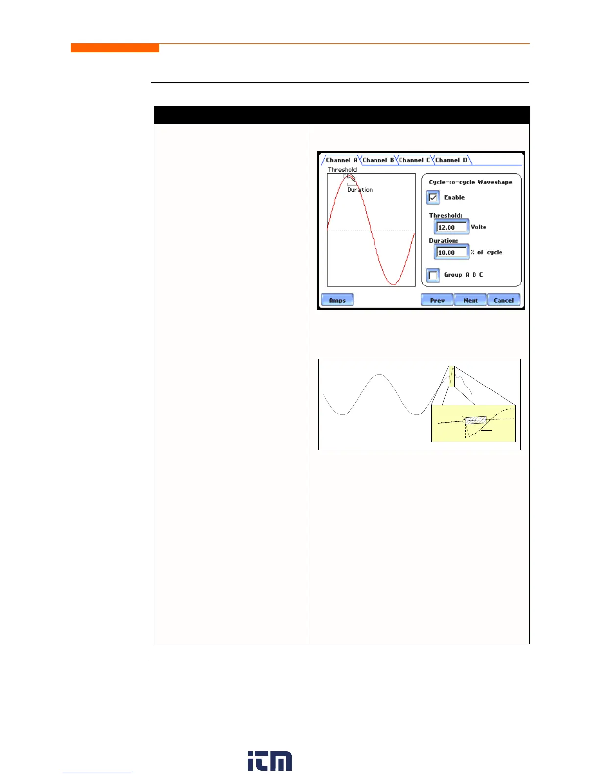
STEP 2: 4400 shows the “floating
window” algorithm used for
waveshape fault detection.
• Press limit field under
Threshold to change limit. Use
the keypad to enter the
threshold limit or tolerance. If
the wave samples differ by
more than the threshold
tolerance for a time exceeding
the duration or window percent
of power frequency cycle, a
waveshape fault is registered.
• Press limit field under
Duration to change limit. Use
the keypad to enter the
threshold duration or window.
• Enable toggles whether this
limit is enabled or disabled.
• Amps toggles between Volts
and Amps.
•Press Group A B C to set
identical waveform threshold
duration values for Channels A,
B and C.
•Press Next to set the rms
distortion waveshape limit.
Proceed to Step 3 on page 6-6.
•Press Prev to return to the
instantaneous peak transient
screen.
•Press Cancel to retain previous
threshold duration and return to
Advanced Options menu.
MARK112_104
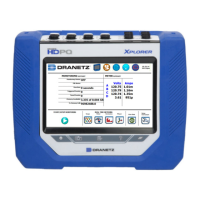
Brief explanation on floating window algorithm:
The figure above helps illustrate the “floating
window” algorithm used for waveshape fault
detection. This window is visualized on screen as
sliding along a waveform, precisely one cycle
behind the previous sample point, v
i
. The height
of the window defines a maximum allowable
voltage deviation in magnitude. The width of the
duration corresponds to a number of sample
points, N. For each sample v
i
, when compared to
v
i-1 cycle
where the deviation in magnitude is
outside the maximum allowable deviation, a
counter is incremented. For each sample v
i
that is
within the maximum allowable deviation, the
counter, if greater than 0, is decremented. If the
count reaches N, a trigger occurs.
Present
Cycle
Previous Cycle
with Floating Window
Trigger
w ww . . co m
information@itm.com1.800.561.8187