62
EU Installations
Hardware Installation (cont.)
4. AUX Power Wiring
UL Installations
The control panel can provide a maximum of 700mA of current for modules, powered detectors, relays, LED’s etc. If the total current
required exceeds 700mA an additional power supply is required (e.g.,PC5200, PC5204). See list below.
NOTE:
Min/max operating voltages for devices, sensors and modules is 9.5VDC - 14VDC.
The control panel provides a maximum of 500mA of current for modules, powered detectors, relays, LED’s etc. If the total current required
exceeds 500mA an additional power supply is required (e.g.,PC5200, PC5204). See list below.
NOTE:
AUX Output voltage: 12VDC, -15%/+10% when Input Voltage is between 85%-110% of rated value and output current between 0.0A -
0.5A max.
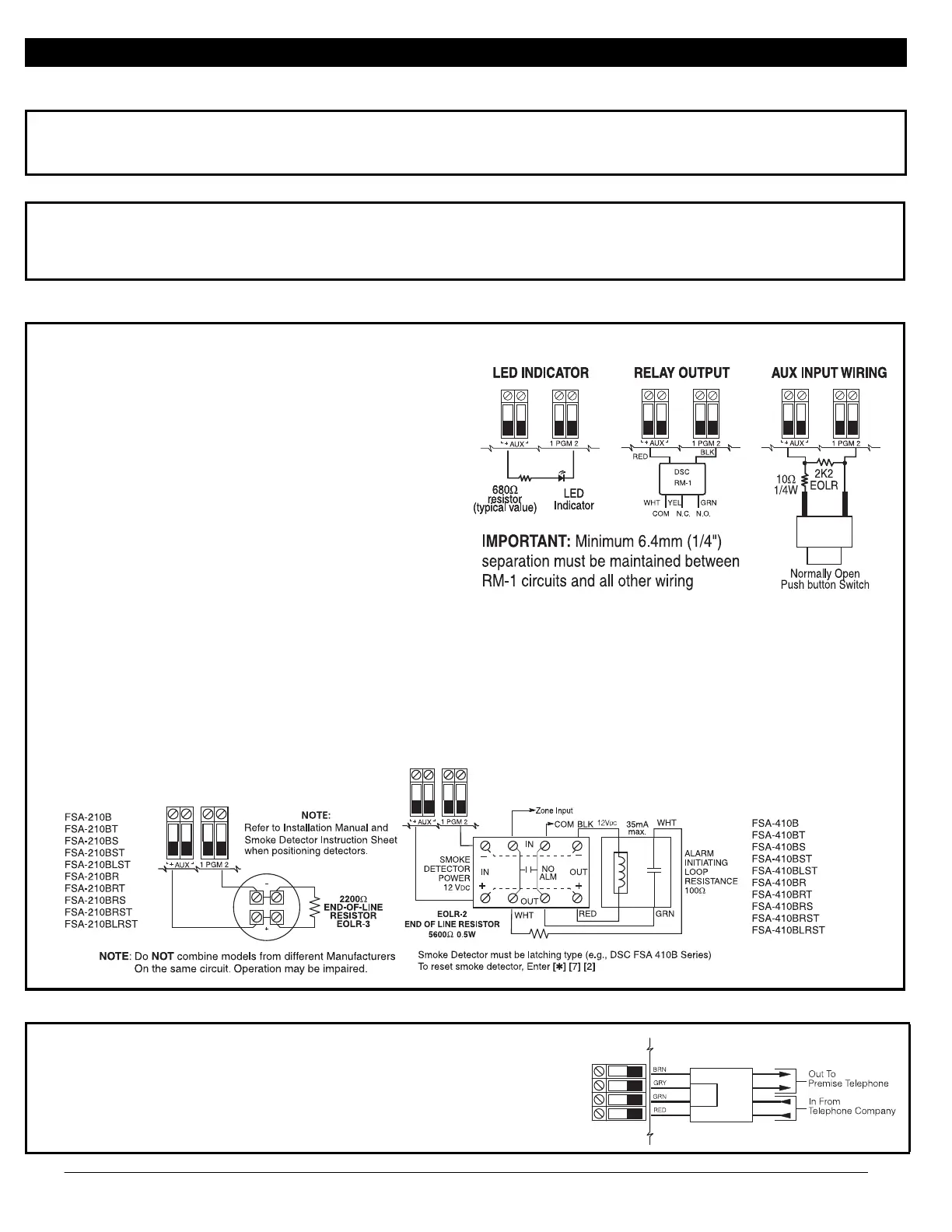
5. PGM Wiring
PGMs switch to ground when activated by control panel.
Connect the positive side of the device to be activated to the AUX+
Terminal. Connect the negative terminal to the PGM.
current output is as follows
• PGM 1, 3, 4 .....................50mA
• PGM 2 ...........................300mA
For currents levels greater than 300mA a relay is required.
PGM2 can also be used for 2-wire smoke detectors.
NOTE: Use SEOL resistors on FIRE ZONES ONLY.
PGM 1, LED Output with current limiting resistor and Optional Relay
driver output
2-wire Smoke Detectors Initiating Circuit
• Style B (Class B), Supervised, Power Limited
• Compatibility Identifier................................................ PC18-1
• DC Output Voltage ............................................9.8-13.8 VDC
• Detector Load .....................................................2 mA (MAX)
• Single-end-of-line (SEOL) Resistor ............................. 2200Ω
• Loop Resistance....................................................24Ω (MAX)
• Standby Impedance ......................................... 1020Ω (ΝΟΜ)
• Alarm Impedance ................................................570Ω (MAX)
• Alarm Current....................................................89 mA (MAX)
• Maximum number of 2-wire Smoke Detectors ................... 18
2-wire Smoke Detectors
Compatibility ID For FSA-210 Series is: FS200
4-wire Smoke Detectors
6. Telephone Line Wiring
Wire the telephone connection terminals (TIP, Ring, T-1, R-1) to an RJ-31x Con-
nector as indicated.
For connection of multiple devices to the phone line, wire in the sequence shown.
Telephone format is programmed in section [350].
Telephone Call Directions are programmed in section [351]-[376].
RM-1/RM-2 POWER LOOP
SUPERVISORY RELAY
Compatible DSC 2-wire smoke detectors:
FSA-210A Series for ULC
FSA-210B Series for UL
FSA-210C Series for EU
Compatible DSC 4-wire smoke detectors:
FSA-410A Series for ULC
FSA-410B Series for UL
FSA-410C Series for EU