5 Programming Worksheets
17
[005] System Times
[009] Main Board PGM Output Programming (PGM 1 & 2)
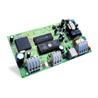
[010] PC5208 PGM Output Programming
Valid entries for Entry Delay are between 030-255. Valid entries for SIA CP-01 Exit Delay are between 045-255.
Default Enter 3 digits from 001-255
Subsection [01]
I___I___I___I Entry Delay 1 030
I___I___I___I Entry Delay 2 045
I___I___I___I Exit Delay 120
Subsection [09]
I___I___I___I Bell Time-out (BTO) 004
Note: If the Exit Delay is silent (Stay Arming Function Key), the exit delay is twice the programmed value but must not exceed 255
seconds (090-255 seconds).
Note: For UL installations, the Entry Delay plus the Transmission Delay must not exceed 60 seconds.
[006] Installer Code [007] Master Code
Default Default
555555 I_______I_______I_______I_______I_______I_______I 123456 I_______I_______I_______I_______I_______I_______I
[008] Maintenance Code
i These codes are 4 or 6-digits (programmed in
Section [701] Opt.[5]. For 4-digit codes, the default is
the first 4 digits.
Default
AAAA00 I_______I_______I_______I_______I_______I_______I
Programmable Output Options
00 Null PGM (Not Used)
01 Burglary and Fire Output
02 Not Used
03 Sensor Reset [*][7][2])
04 2-Wire Smoke
05 Armed Status
06 Ready To Arm
07 Keypad Buzzer Follow
08 Courtesy Pulse
09 System Trouble Output (with Trouble Options)
10 System Event Output (with Event Options)
11 System Tamper (all sources: zones, keypad)
12 TLM and Alarm
13 Kiss-off
14 Ground Start Pulse
15 Remote Operation
16 Not Used
17 Away Armed Status
18 Stay Armed Status
19 Command Output #1 ([*][7][1])
20 Command Output #2 ([*][7][2])
21 Command Output #3 ([*][7][3])
22 Command Output #4 ([*][7][4])
25 Delayed Fire and Burglary Output
26 Not Used
27 Police Code Output
29 Zone Follower Output (Zones 1–8)
30 Status Alarm Memory Output
31-32 Not Used
Default
19 I_______I_______I Onboard PGM 1 Type
10
I_______I_______I Onboard PGM 2 Type
Default
01 I_______I_______I PGM 3
01
I_______I_______I PGM 4
01
I_______I_______I PGM 5
01
I_______I_______I PGM 6
01
I_______I_______I PGM 7
01
I_______I_______I PGM 8
01
I_______I_______I PGM 9
01
I_______I_______I PGM 10
 Loading...
