PC1404
2
Zone Configuration
• 31 zone types and 11 programmable zone attributes
• Supports up to 4 hardwired NC, SEOL, DEOL zones,
expandable to 8 with the zone doubling feature
• Keypad zones allow the system to be configured to support 8
zones—4 onboard zones and up to 4 keypad zones
Access Codes
• Supports 39 user codes and 1 master code
• 6 programmable user code attributes; see PC1404 User
Manual for details
• Duress codes derived from user codes ± 1 digit are not allowed
Programmable Outputs (PGMs)
• Up to an additional 12 PGMs are supported with PGM
expander for a total of 14 PGMs on the system
• 24 PGM types
• PGM 1: 50mA switched
• PGM 2: 300mA current-limited switched. This PGM supports
compatible 2-wire smoke detectors (90mA current limited)
Power Supply
• 1.5A regulated
• Panel current draw:
240 VAC Primary ..............................180 mA(AC)(Max)
120 VAC Primary ..............................400 mA(AC)(Max)
16.5 VAC Secondary .........................2A(AC)(Max)
• Nominal panel current draw: 85mA
• 550mA Auxiliary Supply, 12V
DC
• Positive Temperature Coefficient (PTC) for BELL, AUX+
and battery terminals
• Reverse Battery Detection/Protection
• Supervision for loss of AC power and low battery
• Output ripple voltage 85mV p-p (Max)
Power Requirements
• Transformer = 16.5VAC, 40VA
• DSC PTD1640U, DSC PTC1640U. Transformers must be
Energy Efficient as per the local rules and regulations
• High-efficiency transformer for Australia
Battery
• 12V sealed lead acid battery
• Charging mechanism supports 1.2Ah, 4Ah, 7Ah batteries
• Charging rate: 240mA (12 hrs max.)
• Range for the charge current: 200mA–350mA
• Backup time: 24 hrs
• Replace battery every 3–5 years.
• Low battery trouble indication threshold 11.25V
DC
• Low battery trouble restore threshold 11.75VDC
• Battery deep discharge protection: fixed at 9.6V
Aux+:
• Voltage: 9.6–13.8VDC
• Current: 550mA
Note: Aux and PGM outputs share the 550mA load.
Keybus Terminals
• Clock: yellow
• Data: green
Memory
• 32Kbit serial CMOS EEPROM with write protection
• Retains programming and system status on AC or battery failure
• Data retention: 20 years min.
Bell Output
• 12V, 700mA supervised (1k) bell output (current limited at 2A)
• Steady, pulsed, or temporal three Fire, CO alarm cadences
• Bell short detection
Operating Environmental Conditions
• Temperature range: -10°C to +55°C (14°F-131°F)
• Relative humidity: 93% noncondensing
Telco Terminals
• Ring detection: 30V RMS min
• Protection for high ring voltage - Sidactor
PCB Dimensions
• Length: 153 mm (6.0")
• Width: 94 mm (3.7")
• Height (tallest component): 28 mm (1.1")
System Supervision Features
The PC1404 continuously monitors a number of possible trouble
conditions and provides audible and visual indication at the key-
pad. Trouble conditions include:
• AC Power Failure
• Fire Trouble
• Telephone Line Trouble
• Low Battery Condition
• Bell Circuit Trouble
• General System Trouble (indicates peripheral module trouble)
• General System Tamper (indicates peripheral module tamper)
• Loss of System Time
• Tamper by Zone
• Failure to Communicate
False Alarm Prevention Features
• Audible Exit Delay
• Audible Exit Fault
• Communication Delay
• Entry Delay Urgency
• Quick Exit
• Cross Zone Burglary Alarm
• Rotating Keypress Buffer
Cabinets
Several different cabinets are available for the PC1404. They are
as follows:
PC5003C Cabinet
Cabinet for the PC1404 alarm controller. Dimensions (approxi-
mate): 288mm x 298mm x 78mm /11.3" x 11.7" x 3"
PC500C Cabinet Household Fire and Burglary
Cabinet for the PC1404 alarm controller. Dimensions (approxi-
mate): 213mm x 235mm x 78mm/8.4" x 9.25" x 3.0"
1.3 Out of the Box
Please verify that the following components are included in your
system:
• one PC5003C cabinet
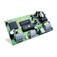
• one PC1404 main control circuit board
• one Installation Manual with programming worksheets
• one PC1404 Quick Reference Guide
• one hardware pack consisting of:
–one 2-wire battery harness; L=34cm black & red
–two kep nuts 6-32
–one screw 6-32 x 1/2" Pan Phillips m/s zinc
–0.35m wire ground TR64 22GU green
–one terminal ring 22/18 #6 Stud
–1 washer tooth-lock 672-030ZP
–four 3/8" nylon standoffs; locking PCB support
–eight 5600 (5.6K) 1/2W 5%TR resistors
–eight 1500 (1.5K) 1/2W 5%TR resistors
–four 2400 (2.4K) 1/2W 5%TR resistors
–one 2200 (2.2K) 1/2W 5%TR resistor
–one 10001/2W 5%TR resistor
Ring R-1
Tip T-1
 Loading...