Installation
45
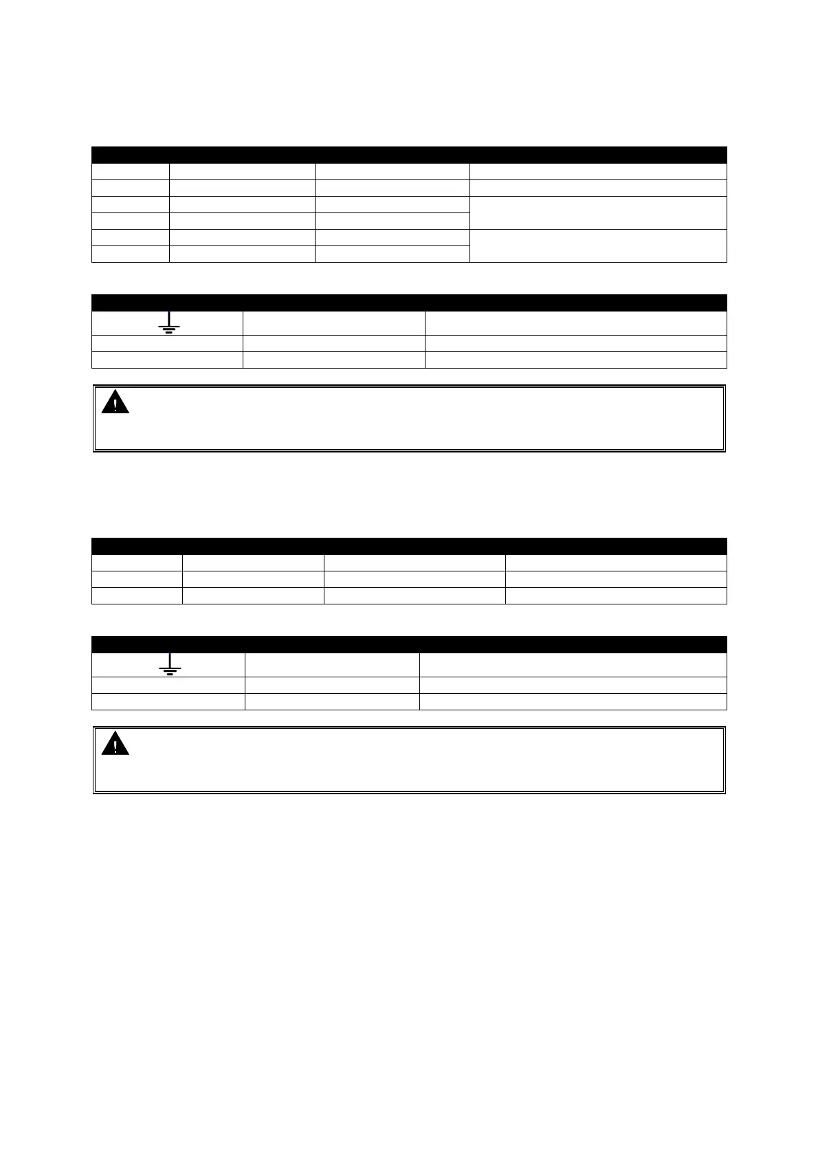
4.2.1 DSE9130, DSE9140, DSE9250, DSE9255 & DSE9260
Connector A
-OP Load negative 1mm² (AWG 16) Battery negative terminal
+OP Load Positive 1mm² (AWG 16) Battery positive terminal
BOOST Boost mode 0.5 mm² (AWG 22)
Connect together for boost operation
BOOST Boost mode 0.5 mm² (AWG 22)
CF Charge failure relay 0.5 mm² (AWG 22)
Closes under charge fail conditions
CF Charge failure relay 0.5 mm² (AWG 22)
Connector B
Earth 1mm² (AWG 16)
N AC Neutral 1mm² (AWG 16)
L AC Live 1mm² (AWG 16)
CAUTION: Ensure Earth Terminal is connected to Battery negative (for negative earth
systems) or Battery positive (for positive earth systems)
Where no system earth exists, Earth Terminal must be connected to battery negative
4.2.2 DSE9150
Connector A
NC Not Connected Do not connect
-OP Load negative 1mm² (AWG 16) Battery negative terminal
+OP Load Positive 1mm² (AWG 16) Battery positive terminal
Connector B
Earth 1mm² (AWG 18)
N AC Neutral 1mm² (AWG 18)
L AC Live 1mm² (AWG 18)
CAUTION: Ensure Earth Terminal is connected to Battery negative (for negative earth
systems) or Battery positive (for positive earth systems)
Where no system earth exists, Earth Terminal must be connected to battery negative