Installation
47
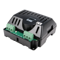
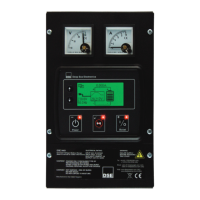
4.2.4 DSE9470 MKII, DSE9472 MKII, DSE9480 MKII, DSE9481 MKII
NOTE: For obsolete parts 9470-001-00 and 9480-001-00 contact DSE Technical Support for
connection details.
Connector A
-OP Load negative 1mm² (AWG 16) Battery negative terminal
+OP Load Positive 1mm² (AWG 16) Battery positive terminal
Connector B
LK1 Configurable Input 1mm² (AWG 16)
Connect the terminals together
to activate the input.
The Factory Setting for the
digital input provides a
selection of 12V / 24V
operation.
Customer configurable using
DSE Configuration Suite PC
Software.
NOTE: Digital Input Not
Fitted to 9470-001-00 and
9480-001-00.
LK1
Configurable Input (0V) 1mm² (AWG 16)
NC
Normally Closed Contact
of the Charge failure relay
0.5 mm² (AWG 22)
Changes State Under Charge
Fail Conditions
COM
Charge failure relay
Contact Common
0.5 mm² (AWG 22)
NO
Normally Open Contact of
the Charge failure relay
0.5 mm² (AWG 22)
NOTE: For further details of PC Configuration, you are referred to DSE Publication: 057-
159 DSE9400 Series Battery Charger Configuration Suite Manual.