Signal Connection to External Devices
▲
■■■■■■■■■■■■■■■■■■■■■■■■■■■■■■■■■■■■■■■■■■■■■■■■■■■■■■■■■■■■■■■■■■■■■■■■■■■
DS1104 Hardware Installation and Configuration March 2004
I■■■■■■■■■■■■■
▼
130
■■■■■■■■■■■■■■■▼
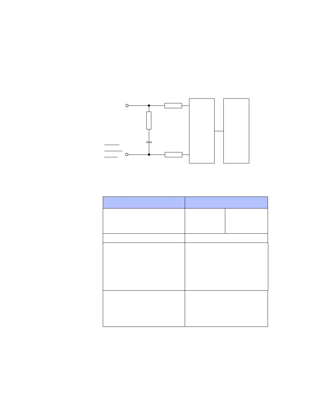
Input Circuit and Electrical Characteristics
Input circuit The following illustration is a simplified diagram of the input circuitry
of the digital incremental encoders.
Electrical characteristics The encoder interface supports single-ended TTL and differential
RS422 signals with the following characteristics.
1 kΩ
150
Ω
1 k
Ω
4.7 nF
RS422/
Single
Ended
Converter
Digital
Converter
Interface
PHI0 (x)
PHI90 (x)
IDX (x)
PHI0 (x)
PHI90 (x)
IDX (x)
Parameter Value
Min. Max.
TTL input voltage High
Low
2.0 V
0V
5.0 V
0.8 V
TTL input resistance 12 kΩ
RS422 input voltage High
Low
Diff > +0.2 V
Diff < -0.2 V
• Diff = Voltage difference between
non-inverted and inverted signal
• The input signal, together with the
corresponding inverted signal, must
be in the range 0 ... 5 V.
RS422 input resistance The input resistance gradually
drops from 8.5 kΩ at the corner
frequency of 28 kHz to 210 Ω
at the corner frequency of
225 kHz.