Connector Pinouts and LEDs
▲
■■■■■■■■■■■■■■■■■■■■■■■■■■■■■■■■■■■■■■■■■■■■■■■■■■■■■■■■■■■■■■■■■■■■■■■■■■■■■■■■■■■■■■■■■
DS1104 Hardware Installation and Configuration March 2004
I■■■■■■■■■■■■■
▼
92
■■■■■■■■■■■■■■■▼
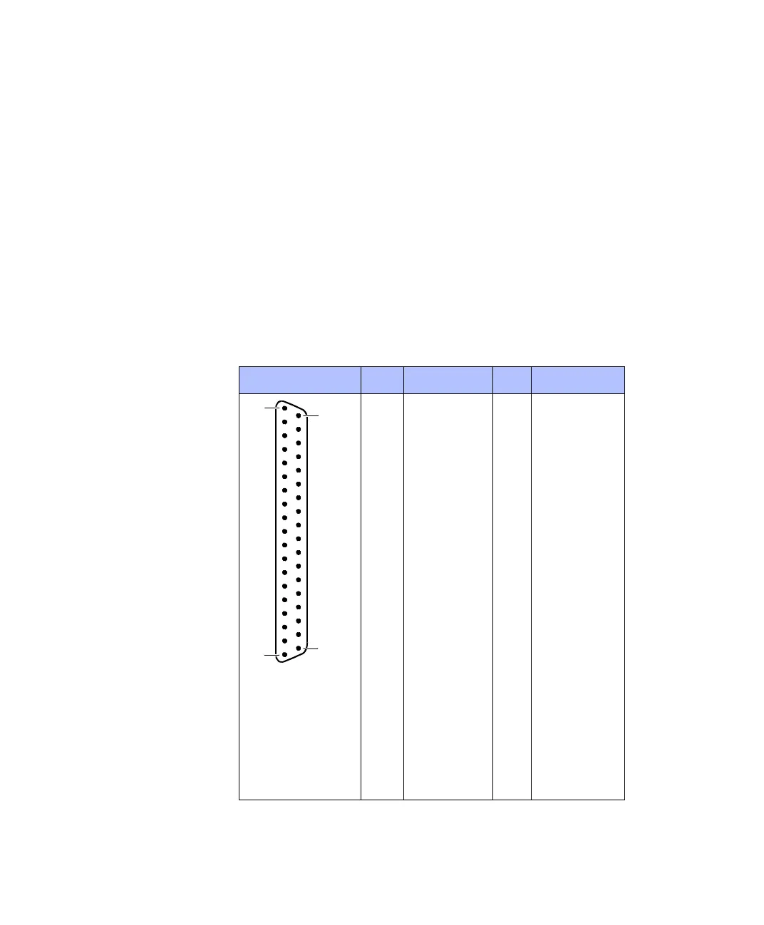
Digital I/O Connector (CP17)
The digital I/O connector (CP17) is a 37-pin, male Sub-D connector
located on the front of the connector panel.
Pinout Because the pin numbering used for Sub-D connectors is not
standardized, the following figure shows the numbering scheme used
(front view).
C
Do not rely on the numbers written on Sub-D connectors.
Connector (CP17) Pin Signal Pin Signal
19 GND
18 GND 37 VCC (+5 V)
17 GND 36 VCC (+5 V)
16 GND 35 GND
15 IO19 34 GND
14 IO17 33 IO18
13 GND 32 IO16
12 IO15 31 GND
11 IO13 30 IO14
10 GND 29 IO12
9IO11 28GND
8IO9 27IO10
7GND 26IO8
6 IO7 25 GND
5IO5 24IO6
4GND 23IO4
3 IO3 22 GND
2IO1 21IO2
1GND 20IO0
1
37
20
19