Connector Pinouts and LEDs
▲
■■■■■■■■■■■■■■■■■■■■■■■■■■■■■■■■■■■■■■■■■■■■■■■■■■■■■■■■■■■■■■■■■■■■■■■■■■■■■■■■■■■■■■■■■
DS1104 Hardware Installation and Configuration March 2004
I■■■■■■■■■■■■■
▼
98
■■■■■■■■■■■■■■■▼
UART RS232 Connector (CP21)
The UART RS232 connector CP21 is a 9-pin, male Sub-D connector
located on the front of the connector panel. The pinout has been
adapted from the 9-pin RS232 connector of a PC.
N
The DS1104 supports one serial interface. In RS232 mode the signals
are available from the RS232 connector CP21. In RS422/485 mode the
signals are available from the RS422/485 connector CP22. CP21 and
CP22 are mutually exclusive and cannot be used at the same time.
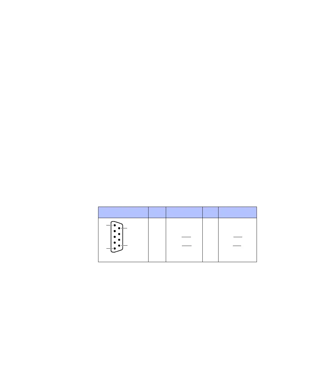
Pinout Because the pin numbering used for Sub-D connectors is not
standardized, the following figure shows the numbering scheme used
(front view).
C
Do not rely on the numbers written on Sub-D connectors.
Signal names in parentheses apply when the UART is set to the RS422
or RS485 mode. However, you should use the UART RS422/RS485
Connector (CP22) instead, when you are using RS422/485 mode.
For detailed information (I/O circuits, electrical characteristics, etc.) on
the I/O lines terminating at this connector, see Serial Interface on
page 136.
Connector (CP21) Pin Signal Pin Signal
5GND
4 DTR (TXD) 9 Not used
3TXD (TXD
) 8 CTS (CTS)
2 RXD (RXD
) 7 RTS (RTS)
1 DCD (CTS) 6 DSR (RXD)
5
1
6
9