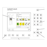
17. Controls and control panel EFKA
In these Service Instructions only the most important items in the
controls are described.
Please find the comprehensive description in the enclosed operating
instructions of the motor manufacturer.
17.1 Positioning
17.1.1 Defining the positions
Reference position
The reference position is the starting position for all other positions. It is
defined as the position of the needle tip, with the needle descending in
the normal direction of rotation, at the level of the upper side of the
needle plate. With the control c orrectly set only the reference position
needs to be reset after the removal of the proximity switch: all other
positions are then automatically correct.
Position 1
In position 1, the bottom edge of the needle eye of the lowered needle
must be in the same height as the shuttle plunger ring.
Position 2
In position 2 the thread lever is shortly after the upper dead center.
(The thread must be cut.)
17.1.2 Adjusting the positions (DC1600/DA82GA)
Once every rotation the digital proximity switch sends 512 pulses
(increments) and one extra pulse to the control. All needle
positions are determined by these pulses and the values
of parameters F-170 and F-171.
The proximity switch requires no mechanical adjustment.
Caution !
All positions must be reset after:
1. the sewing drive has been operated for the first time
2. the sewing drive, drive control or drive control plate
have been replaced
3. the EPROM in the drive control has been replaced.
Only the reference position must be reset after:
1. Removing and mounting or replacing the synchronizer.
72
 Loading...


