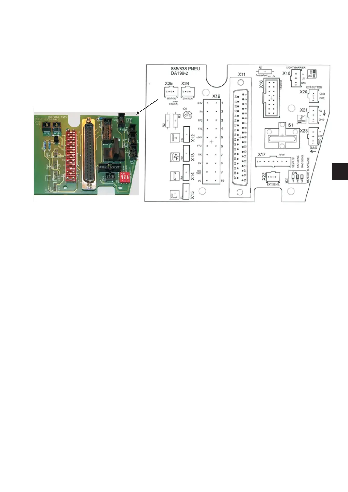
8.2 Terminals to PCB connections - pneumatic variant
Description of DA199_2 (9850 838000) switchboard
X11 - 37-pole connector (to control box)
X12 - thread tensioner valve
X13 - secondary thread tensioner valve
X14 - bartacking valve
X15 - sewing foot valve
X16 - keypad
X17 - bobbin thread monitor
X18 - light barrier
X19 - 1. +24V
2. FA (thread trimming)
3. FF3 (functional outlet 3, e. g. puller, pneumatic material edge trimmer)
4. STL (stitch length valve)
5. +24V
6. FF2 (functional outlet 2)
7. NK (needle cooling)
8. FK (thread clamp)
9. /DB3000 (needle switch off)
10. 0V
FW/STL(FA) – auxiliary outlet (thread wiper/zero stitch length at thread trimming)
X20 - external outlet controlled with auxiliary pushbutton on keypad (Imax=50mA)
X21 - connection of auxiliary cable for bottom distribution (FA, +24V, GND)
X22 - external blocking of operation (e. g. thread lever guard switch, etc.)
X23 - connection of a side DAC switchboard (direct drive)
X24 - material edge trimmer microswitch
X25 - material edge trimmer mini motor
S1 - tilt sensor
S2 - sewing machine operation blocking mode; switch in ON position means that the sensor is without function
SENS. S1 = tilt sensor on switchboard; EXT.SENS. = sensor in connector X22
DAC SENS. = sensor on DAC side switchboard (direct drive)
47
EN
 Loading...