Maintenance Manual (960-946) 4-30
Replacement Procedures
4.24 DC IN jack
4.24.1 Removing the DC IN jack
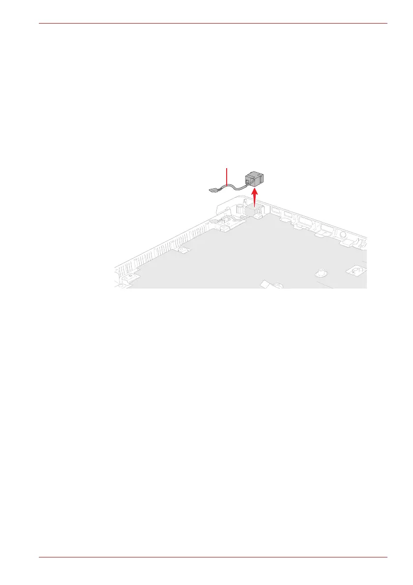
To remove the DC IN jack, follow the steps below and refer to Figure 4-34.
1. Release three screws securing the right display hinge and rotate the
display hinge to upright position.
2. Release the DC IN jack harness from the guide, and remove the DC IN
jack from the slot on the Cover Assembly.
Figure 4-34 Removing the DC IN jack
4.24.2 Installing the DC IN jack
To install the DC IN jack, follow the steps below and refer to Figure 4-34.
1. Set the DC IN jack to the slot on the Cover Assembly and arrange the
DC IN jack harness to the guide.
2. Rotate the right display hinge to original position and secure it with
three screws.
4.25 USB board
4.25.1 Removing the USB board
To remove the USB board, follow the step below and refer to Figure 4-35.
1. Release three screws securing the left display hinge and rotate the
display hinge to upright position.
2. Remove the following screws and the USB board from the Cover
Assembly.
 Loading...