5● Installation DYNACO USA
22 THE SAFEST CHOICE Slimline Series RevB.doc1
5.9 Electrical connection.
Install the control box at a location agreed with the user.
Check that the power supply agrees with the connections of the transformer, motor and frequency
inverter. If necessary, modify.
Connect the following in accordance with the electrical diagram and the specific notes supplied
with the door:
• The motor
• The switch of the absolute encoder, that fixes the end positions of the door.
• The safety equipment, such as the photoelectric cell, the proximity sensor
• The various operating controls.
Activate the emergency stop button and check whether the magneto-thermal main switch is off.
Check that the power cable is not 'live' and connect the switch to the power supply.
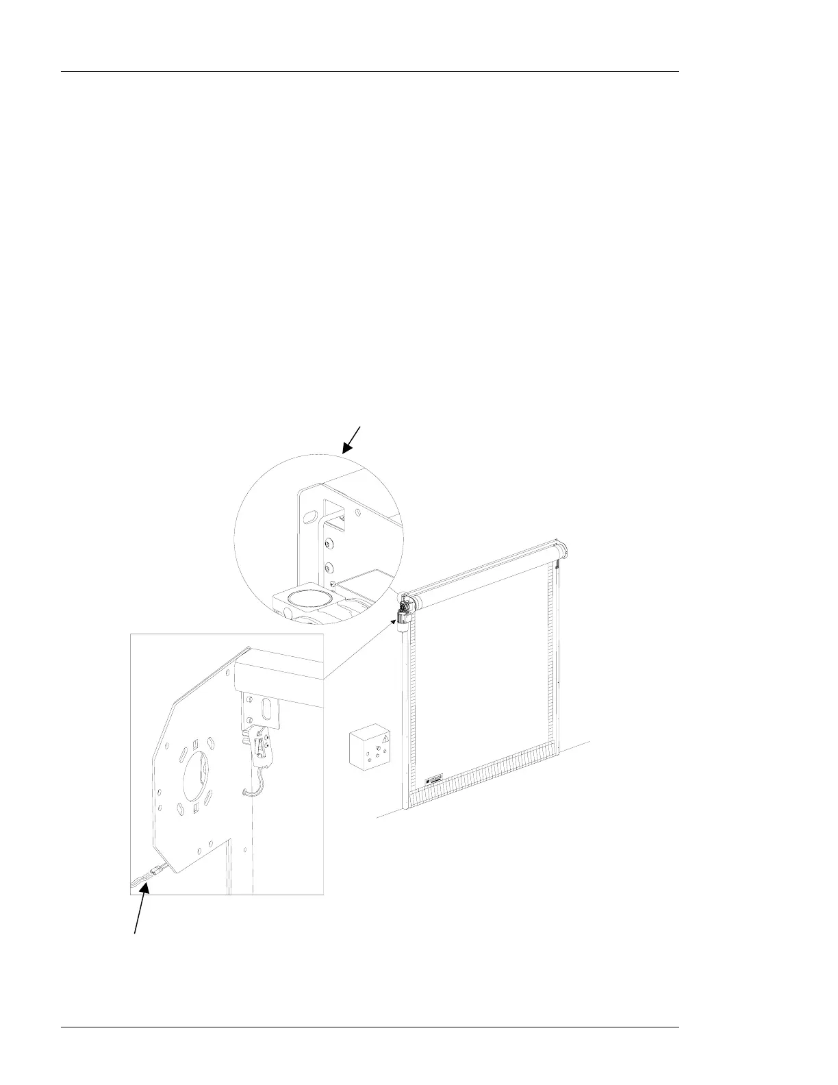
An opening has been provided in the side plate
to pull the cables through the sealing beam.
Figure 5-8: Electrical connection.
Connect the blue and black wires to terminals
16 and 17 of the control box.
 Loading...