DYNACO USA 6 ● DYNALOGIX II (DY 4000)
Slimline Series RevB.doc THE SAFEST CHOICE 39
6.3.2 Install and Test Activation Accessories
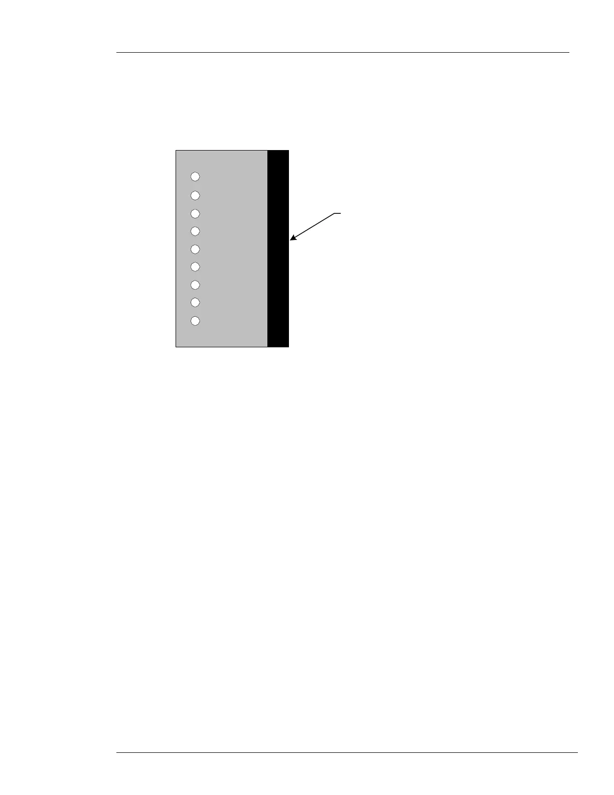
The DYNALOGIX II has nine inputs. Inputs are signals coming to the DYNALOGIX II that get
interpreted to create a certain response. For example, if a pull cord is wired to terminal 2, pulling the
cord sends a signal to the DYNALOGIX II. The DYNALOGIX II knows what the signal based on the
assigned input (terminal 2), thus moving the door up or down. All the inputs have indicator lights and
identification. See Figure 6-16.
Nine Inputs
with Identification
and Indicator Lights
M-00099
06/09/05
I
N
P
U
T
S
2
3
4
5
6
7
8
9
10
PULL CORD/PB
MOTION/LOOP
REV EDGE
PHOTO
DRIVE ERROR
OPEN PB
CLOSE PB
E-STOP/RESET
IN 1
Figure 6-16: Accessory Inputs
See the appendices of this manual and/or the accessory’s documentation from the
manufacturer for installation instructions.
Caution: Install, connect, and then test each of the activation accessories individually before
proceeding to the next accessory. This allows troubleshooting of each component individually.
 Loading...