6● DYNALOGIX II (DY 4000) DYNACO USA
32 THE SAFEST CHOICE Slimline Series RevB.doc1
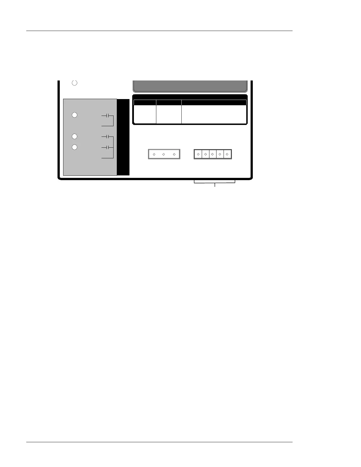
2. Insert the green connector into the DYNALOGIX II. See Figure 6-8.
M-00109
06/14/05
O
U
T
P
U
T
S
ALWAYS INSPECT DOORS FOR PROPER OPERATION
AFTER RESETTING ANY ALARM CONDITION
REFER TO OWNERS MANUAL FOR FURTHER DETAILS. 1-800-459-1930
TYPE COLOR
LED STATUS
CONDITION
TYPE
GREEN
RED
FLASH
RED
CONDITION
CONDITION
INPUT
INPUT
INPUT
OUTPUT
NORMALLY OPEN INPUT TRIGGERED
NORMALLY CLOSED INPUT TRIGGERED
ALARM CONDITION – CHECK INPUT
OUTPUT RELAY IS ENERGIZED
POWER ENCODER
11
12
13
14
15
OUT 1
COM 1
OUT 2
OUT 3
COM 2/3
24VAC
1X2GND
S
H
L
DA-
G
N
DA+
+
12
W
H
T
S
H
L
D
B
L
K
R
E
D
G
R
N
Insertion Point for
Green Connector
Figure 6-8: Insertion Point for Green Connector
6.2.3 Run Wire for Accessories
Run the wiring for the activation accessories but do not connect them. See the appropriate
appendices in this manual for wiring. Connect the activation accessories after the DYNACO installer
has finalized the door.
 Loading...