6● DYNALOGIX II (DY 4000) DYNACO USA
28 THE SAFEST CHOICE Slimline Series RevB.doc1
6.2 Electrical Installation
Warning: Ensure that the power supply shipped with the door is compatible with the transformer,
motor and inverter.
Frequency Inverter Voltage Range:
575 V = 3 Phase
480 V = 3 Phase
230 V = 1 to 3 Phase
208 V = 1 to 3 Phase
Failure to ensure compatible power supply may result in fire and will damage the door.
Caution: Ensure that the electrical installation for this door complies with the National Electrical
Code (NEC) and/or your local electrical code.
Caution: Refer to the electrical schematic shipped with the door for appropriate circuit protection.
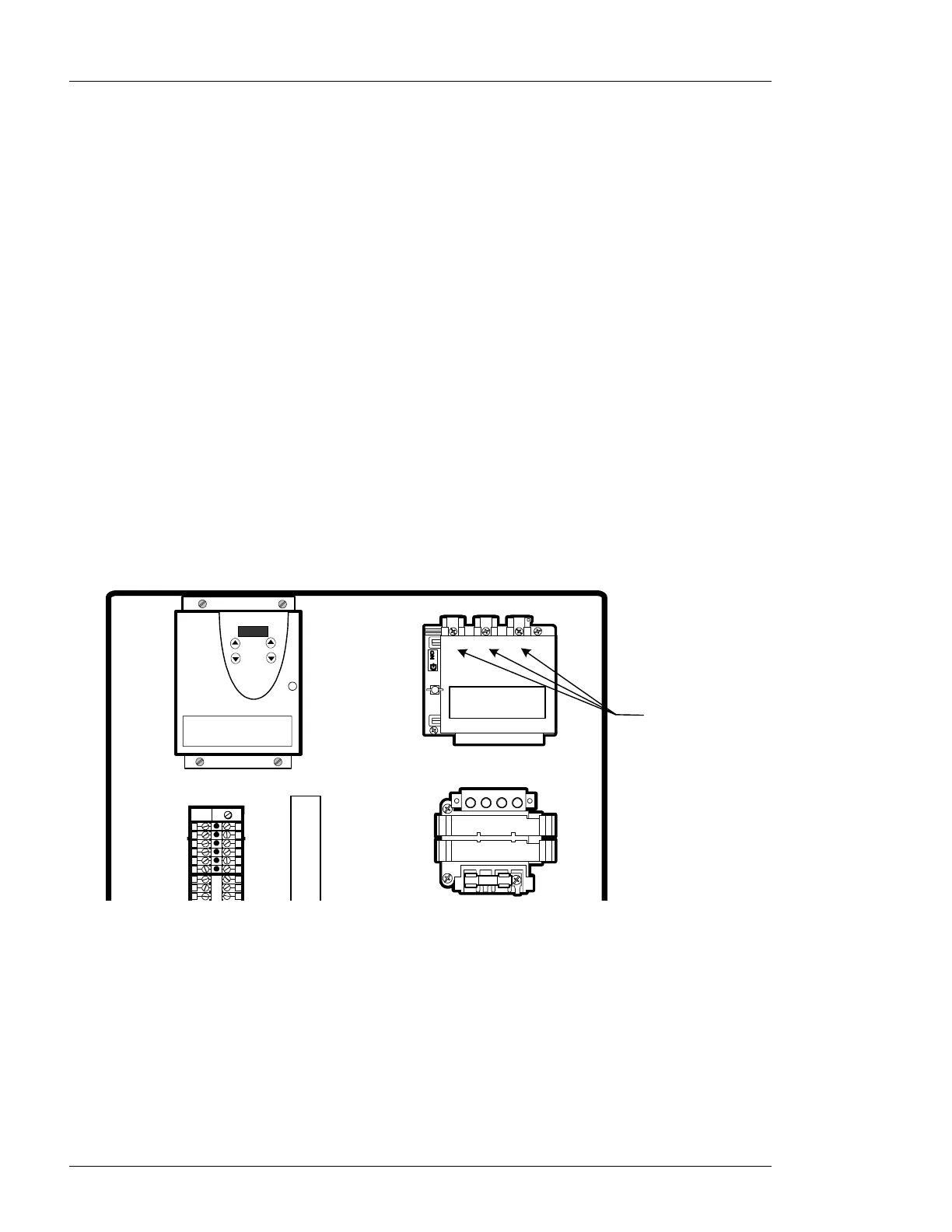
6.2.1 Make the Primary Connections
1. Connect the incoming power. Run the wires (conduit) through the bottom of the Control Box, up
the left side, and connect them into the fused disconnect. See Figure 6-2.
• For a 3-phase unit, use terminals L1, L2, and L3.
• For a 1 or 2-phase unit use terminals L1 and L2.
L1 L2 L3
M2-00107
06/14/05
Power
Connections
Figure 6-2: Power Connections in Control Box
 Loading...