DYNISCO UPR800 Series Instruction Manual
Page | 33
parameter, or press the RESET key to go back to the active display. When set to Auto,
Group 4 Parameter LINE.R displays the detected Line Frequency.
8.2.5 Setting the Display Filter
Filtering is an electrical method of averaging the displayed values over a period of time to
arrive at a more legible display. Filtering helps to eliminate short duration transients and
spikes that may cause false or spurious readings.
To change or view the Main Analog Output Filter, press the FUNC key until nonE and
GROUP show on the display. Press the t key until 2 shows in the upper display. Press
the FUNC key until the lower display changes to DSP.FL. Using the u or t keys, select
the amount of filtering desired, from none (OFF) to five seconds. When finished, press
the FUNC key to lock in the value and advance to the next parameter.
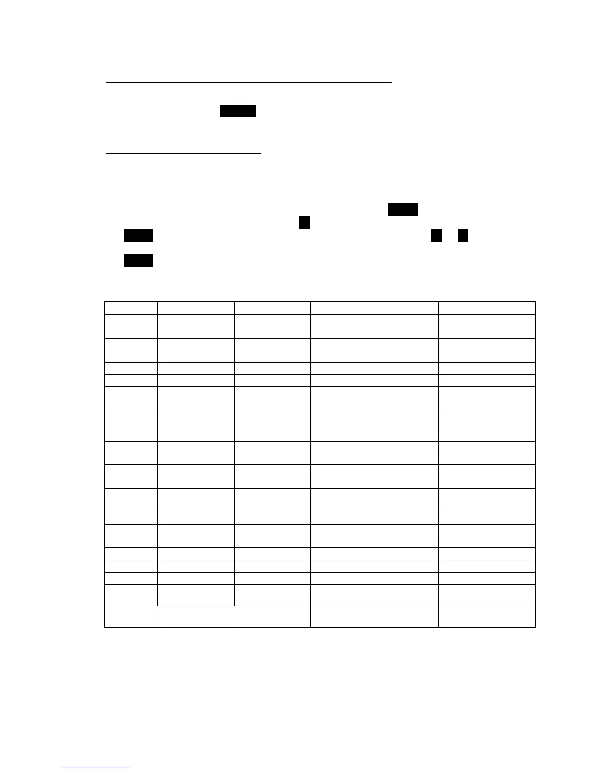
Group 5 Primary Input PI.TYP Str, 0-20, 4-20, 0-5, Str
Selection 0-10
Group 5 Secondary Input SI.TYP OFF, tc, rtd, 0-20
Selection 4-20, 0-10, str Tc
Group 4 Shunt Calibration SHUNT OFF, On On
Group 4 Shunt Value SHNT% 40.0 TO 100.0% 80.0%
Group 3 Input Full Scale
Value
PI.FSV 10 TO 99950 10000
Group 3 Input Low Scale
Value
PI.LSV ± 25% OF SFV 0
OF FS V
Group 3 Input Decimal PI.DP None, 1,2,3,4 None
Point Position places
Group 3 Secondary Input Sl.TC tc J, tc CA, tc L, tc n tc J
T/C Type
Group 3
OFF, Prl.ln, Sec.ln Prl.ln
Channel Link
Group 3
OFF, Prl.ln, Sec.ln PrLIn
Channel Link
Group 3
HI, 10, lnhib HI
Group 2 Zero Calibration ZERO.C OFF, On, CLEAr OFF
Group 2 Span Calibration SPAN.C OFF, On, CLEAr OFF
Group 1
TO 110%of span 40% of range of related
TO 110% of span 60% of range of related
In this example, these are functions necessary to allow operation of a pressure/temperature indicator with
two high alarms.

 Loading...