IL17569
Page 5-42
Effective June, 2001
Output Rly3, The settings for these output relays are set the
Output Rly4, same way as the Output Trip1 relay settings
Output Rly5: shown above, except that these relays have
no Monitor setting.
Output Alarm
The Output Alarm relay settings are set the same way as the Output
Trip1 relay settings shown above, except that the alarm relay does
not have a Monitor setting.
Output Aux LED
This setting determines what logic function controls the lighting of
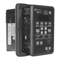
the yellow Auxiliary LED located on the front panel of the FP-5000.
This setting contains the settings: Function, IN1, IN2, IN3, and IN4,
which are set the same as the Output Trip1 settings shown above.
Trip Indicator
The trip indicator function reports the presence of a trip
condition. This setting is programmed to operate based upon the
operation of the output relays (Trip1, Trip2, Rly3, Rly4, Rly5, Alarm,
and Healthy). This setting consists of the settings below.
Dropout: Set to Latched or Unlatched. This setting
determines if the trip indicator stays active
after a trip event clears.
Latched setting means that the Trip Indicator and the
appropriate trip indicator LED lights on the front panel will stay
latched until a “Reset” is initiated either manually or remotely.
Unlatched setting means that the state of the Trip Indicator
directly follows the state of the associated output relay.
Trip1: Set to enable or disable.
Trip2: Set to enable or disable.
Rly3: Set to enable or disable.
Rly4: Set to enable or disable.
Rly5: Set to enable or disable.
Alarm: Set to enable or disable.
Healthy: Set to enable or disable. The indicator is active
when the Healthy Alarm is de-energized to
report a failure.
The default configuration sets the Dropout to “Latched” and enables
the Trip Indication when Trip1 or Trip2 output relays are energized.
Alarm Indicator
The Alarm indicator function reports the presence of an alarm
condition. This function is set the same way as the Trip Indicator.
See Trip Indicator settings above. The default configuration sets the
Dropout to Latched and enables the Alarm Indication when the
Alarm Output relay is energized or the Relay Healthy output relay is
de-energized.
Pickup Indicator
The Pickup Indication function reports a pickup of the programmed
protective functions. The pickup indicator is active for the protective
functions that are enabled in the settings.
Dropout: Set to Latched or Unlatched. This setting
determines if the pickup indicator stays active
after a pickup event. This Dropout setting
works exactly the same as the Dropout setting
in the Trip Indicator settings shown above.
IOC: Set to enable or disable.
TOC: Set to enable or disable.
Volt: Set to enable or disable.
OverFreq: Set to enable or disable.
UnderFreq: Set to enable or disable.
Unbalance: Set to enable or disable.
Prot Alarm: Set to enable or disable.
The default configuration sets the Dropout to Unlatched and
enables all protective functions except the Prot Alarm setting.
See Section 9.2 for more information on configuring the outputs.
5.5.7 Programmable Logic Settings
The programmable logic settings consist of settings for six logic
gates, six timer gates, two latches, twelve blocking gates, and
seven output gates. The seven output gates (Output Trip1, Output
Trip2, Rly3, Rly4, Rly5, Output Alarm, and Output Aux LED) are
configured by the “Output Config” settings described previously,
therefore they won”t be discussed in this section.
See Section 9, Programmable Logic Application, for detailed
information about the logic functions. This section will only describe
how to set the programmable logic settings. Figure 5-3 Logic
Setting Flowchart, on the following page, shows an example of how
to program Logic Gate 1.
The Figure 5-3 flowchart is an example of programming Logic
Gate 1 to be a NAND gate of setting group 2 with IN1 “Trip G OC.”
1. Select programmable Logic from the “Setting Main” setting
display menu and press “Enter PB.”
2. Select Logic Gate 1 press “Enter PB.”
3. Press “Enter PB” and choose Function to be NAND with up/
down PBs, press “Enter PB.”
4. Select Set Group using up/down PBs, press “Enter PB”, choose
Set Group to 2 using up/down PB”s, press “Enter PB.”
5. Select IN1 using up/down PBs, press “Enter PB.”
6. Select Trip using up/down PBs and press “Enter PB.”
7. Select G OC using up/down PBs and press “Enter PB.”
8. Select G OH to be Direct, then press “Enter PB”, which finishes
Logic Gate 1 programming.
Press “Previous PB” to back out of Logic Gate 1 programming and
return to “Programmable Logic” display to program other logic gates.

 Loading...


