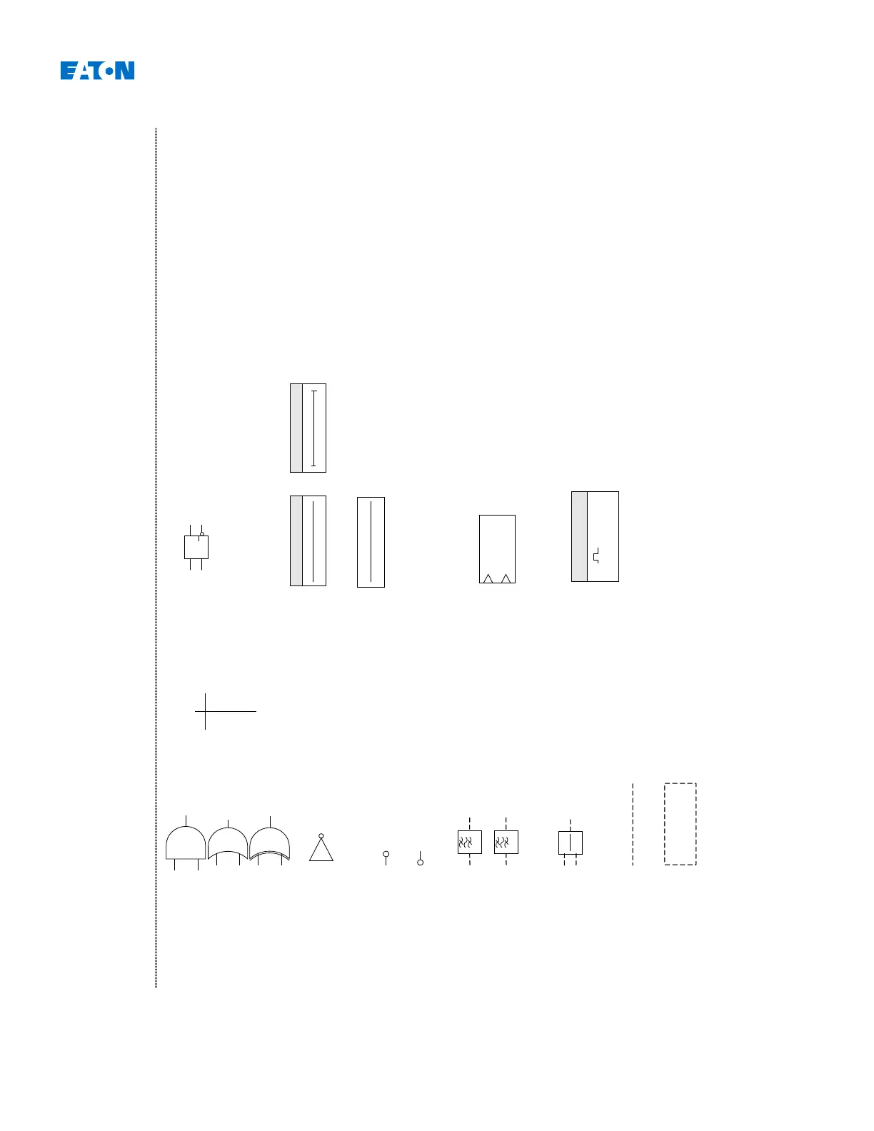
And
Or
Negated Input
Negated Output
Band-pass (filter)
IH1
Band-pass (filter)
IH2
Quotient of Analog Values
t1
Delay Timer
1
Bkr.t-TripCmd
t
Analog Values
AND
S Q
R1 Q
a
b
c
d
RS flip-flop
a b c d
0 0 Unchanged
0 1 0 1
1 0 1 0
1 1 0 1
Time stage: A "1" at the
input starts the element. If
the time <name>.t is
expired, the output becomes
"1" too. The time stage will
be reset by "0" at the input.
Thus the output will be set to
"0" at the same time.
Time stage minimum pulse
width: The pulse width
<name>.t will be started if a
"1" is feed to the input. By
starting <name>.t, the
output becomes "1". If the
time is expired, the output
becomes "0" independent
from the input signal.
IH1
IH2
Exclusive-XR
Analog Value
Comparator
+
R
+ Increment
R Reset
Edge triggered counter
IH2
IH1
OR
XOR
Inverting
t2
t1: Switch On Delay
t2: Switch Off Delay
Delay Timer
t1
t2
t1
t2
Counter

 Loading...


