EDR-5000 IM02602007E
Input, Output and LED Settings
Digital Input Configuration
The State of the Digital Inputs can be checked within menu:
[Operations/Status Display/Name of the assembly group (e.g. DI-8X)]
The Digital Inputs can be configured within menu:
[Device Para/Digital Inputs/Name of the assembly group (e.g. DI-8X)/Group X]
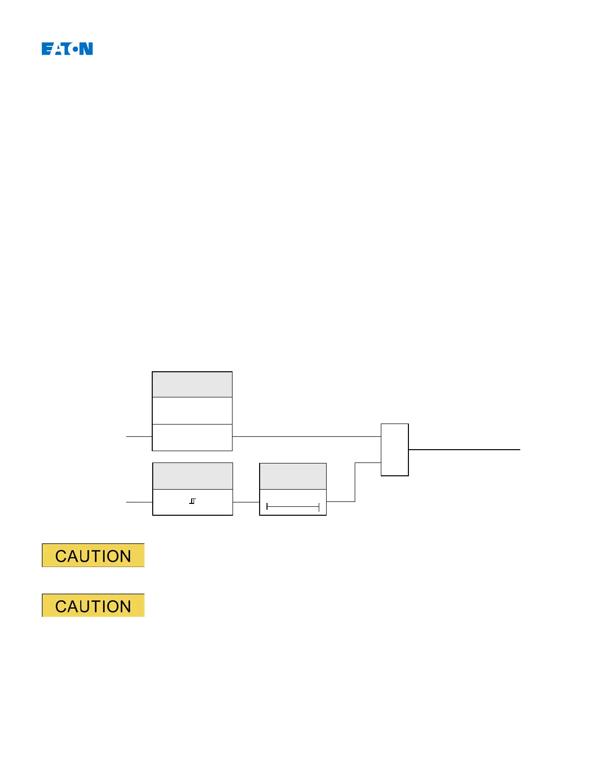
Set the following parameters for each of the digital inputs:
•
»Nominal voltage«;
•
»Debouncing time«
: A state change will only be adopted by the digital input after the debouncing time has expired;
and
•
»Inverting«
(where necessary).
The debouncing time will be started each time the state of the input signal alternates.
In addition to the debouncing time that can be set via software, there is always a
hardware debouncing time (approx 12 ms) that cannot be turned of.
www.eaton.com 73
=1
XOR
State of the Digital Input.
Inverting
Input Signal
Nom Voltage
0t
Debouncing Time
DI Slot X.DI x
Active
Inverting
Inactive

 Loading...


