INSTALLATION
EATON BladeUPS
®
(12 kVA) User's Guide S 164201649 Rev 4www.eaton.com/powerquality
35
13. Parallel or parallel-ready system only. If you are installing other X-Slot cards besides
the Powerware Hot Sync CAN Bridge Card, skip to Step 16.
NOTE Leaving the UPS unattached allows you to adjust the UPS position in the rack for any clearance
needed to install the X-Slot cards.
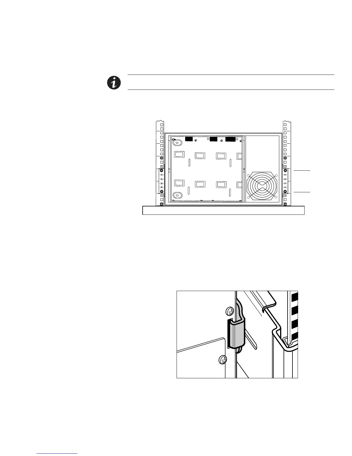
14. Using four M5 machine screws, secure the front of the cabinet to the rack as
shown in Figure 23.
Position 9
Position 4
M5 Screws
Figure 23. Securing the Front of the UPS
15. Insert the two rear hold-down brackets on the rails into the slots on the rear of
the cabinet (see Figure 24).
If necessary, push out on the rack upright to allow the clearance needed to insert
the bracket. The rack upright flexes easily.
Verify that the brackets seat firmly, then tighten the nuts on the rear hold-down
brackets. The UPS is now secured in the rack.
Figure 24. Inserting the Rear Hold-Down Bracket

 Loading...


