INSTALLATION
EATON BladeUPS
®
(12 kVA) User's Guide S 164201649 Rev 4www.eaton.com/powerquality
46
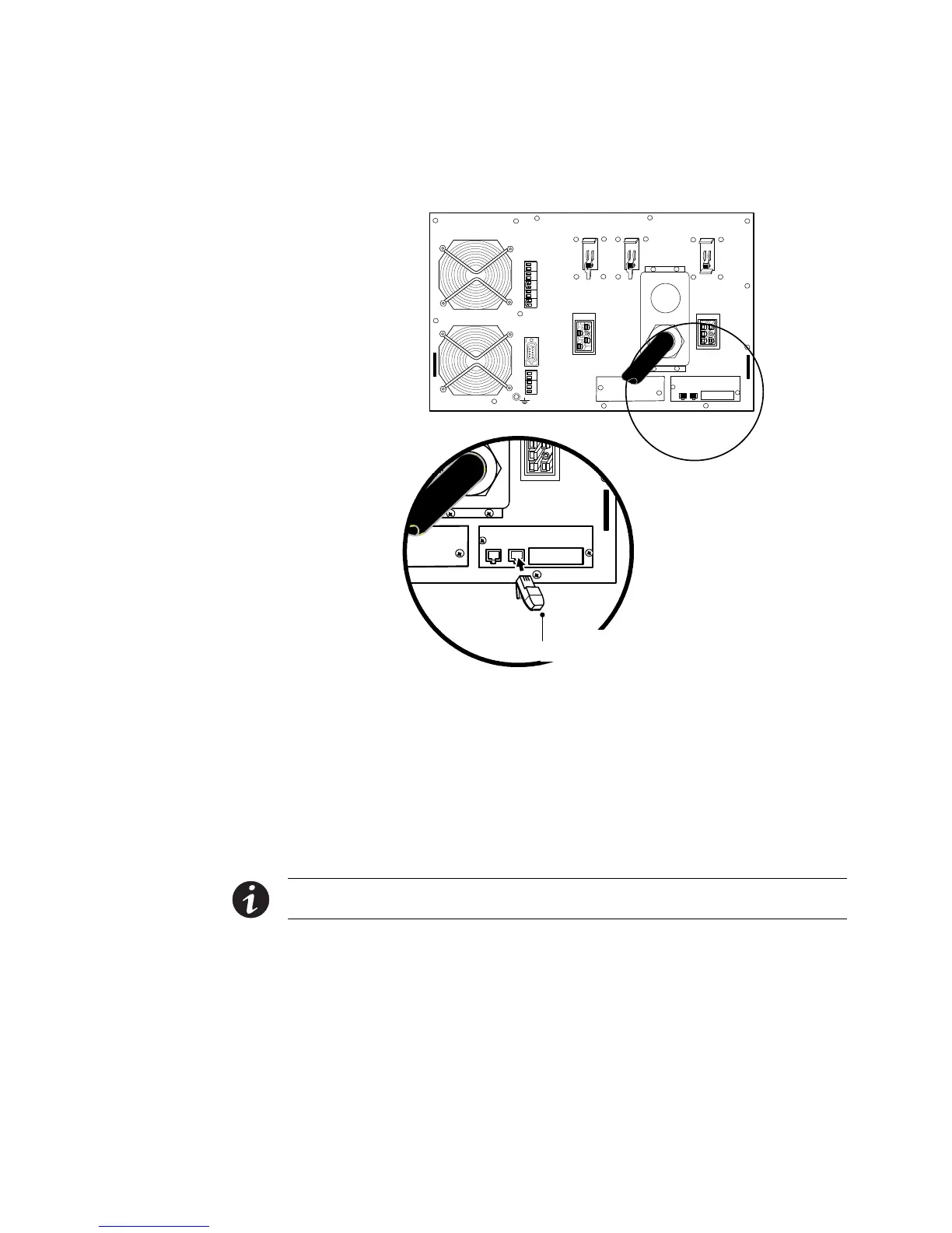
9. Install the second supplied blue terminating plug (see Figure 35) into the
CAN OUT port on the last UPS (UPS 3 in Figure 36).
SHIELD
CAN H
CAN L
TX
TX
NO
COM
NC
ALR RTN
ALARM
CAN OU T
CAN IN
Blue Terminating Plug
(CAN OUT)
Figure 35. Installing the Blue Terminating Plug ( Last UPS)
10. Verify that only the first and last UPSs in the configuration have a blue
terminating plug installed.
11. Using the supplied connectors, install a CAN Bridge Card cable between each
UPS as shown in Figure 36, connecting the CAN OUT port on one UPS to the
CAN IN port on the next UPS.
On startup, the parallel system will identify the UPS wired after UNIT 1 as
UNIT 2, and so forth.
NOTE You can configure the parallel system with UPS 1 at the bottom of the rack (as shown in Figure 36) or
at the top of the rack.

 Loading...


