INSTALLATION
EATON BladeUPS
®
(12 kVA) User's Guide S 164201649 Rev 4www.eaton.com/powerquality
47
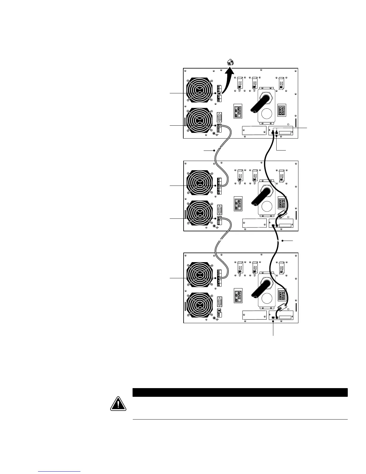
UPS 3
UPS 2
UPS 1
CAN Bridge Card Cable
CAN
IN
Blue Terminating Plug
Redundant Signal Cable
For Parallel
Use Only
Standalone/
Parallel
For Parallel
Use Only
Standalone/
Parallel
Standalone/
Parallel
(remove)
CAN
OUT
Blue Terminating Plug
Figure 36. Typical CAN Bridge Card and Redundant Signal Wiring
12. Install a redundant signal cable between the For Parallel Use Only and
Standalone/Parallel terminals on each UPS as shown in Figure 36.
Be sure to check correct polarity when installing the cable.
C A U T I O N
If polarity or wiring is not correct, the parallel system does not operate normally. For example, when shutting
down one UPS, the remaining UPS transfers the load to bypass instead of supporting the load. Verify that all
wiring is correct for proper operation.
13. Remove the Standalone/Parallel terminal block connector from the last UPS
(UPS 3 in Figure 36).

 Loading...


