10 S611 Soft Starter MN03902011E—May 2012 www.eaton.com
Control Wiring Inputs
Control wiring is connected to the S611 by terminal blocks located at the front of the unit.
Using the wiring diagrams below and on Pages 12–14, and table on Page 11 as guides,
connect the control wiring as required for your application. Failure to follow this caution may
result in severe damage to the controller.
Control Wiring Terminal Blocks
CAUTION
Only apply 120 Vac 50/60 Hz to terminal blocks 1, 2, and 3
(TB1, TB2, TB3). All control wiring is 22–12 AWG
(0.33–2.5 mm
2
).
Do not apply 120 Vac to comms port A terminal block 4
(TB4).
F1F2
Relays
N–Network
Ground
N–Tap
Neutral
L–Tap
Line
L–Network
N–Permissive
L–Permissive
N–Start
L–Start
N–Reset
L–Reset
TB2
TB1
TB3
120 Vac
Control
120 Vac
Supply
98 97
Relay 2 Relay 1
96 13 14
Comms Port B
TB5 (Connector)
+24V
D0
D1
Common
TB4
Comms Port A
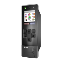
User Interface
Module
www.comoso.com

 Loading...


