S611 Soft Starter MN03902011E—May 2012 www.eaton.com 15
120 Vac 50/60 Hz Control Power
The S611 soft starter requires 120 Vac 50/60 Hz control
power. The sealed in and inrush characteristics of the S611
soft starter are summarized in the table below:
Control Power Requirements
For applications where one starter is used with one control
power transformer (CPT), the CPT selected must be equal to
or greater than both the sealed in and inrush requirements of
the starters.
●
Max steady state for the CPT * sealed in power of the
starter
●
Outrush for the CPT * inrush power of the starter
Multiple starters can be used with one CPT. If the application
requires the starters to start at the same time, the CPT must
be sized for the sum of the sealed in and inrush power for
each starter.
●
Max steady state for the CPT * sum of the sealed in power
of all the starters
●
Outrush for the CPT * sum of the inrush power of all the
starters
Formulas to calculate control power requirements are as
follows:
●
Definitions:
●
SI = Sum of seal incurrent
●
LS = Largest seal incurrent
●
LI = Largest inrush needed
●
TS = Total seal incurrent needed
●
LO = Largest outrush needed
●
TS = (SI – LS)
LO = TS + LI
●
Max steady state for the CPT * SI
●
Outrush for the CPT * LO
The voltage on the S611 control power supply and control
input terminals must be 120 Vac ±10% to provide proper
operation of the soft starter.
Control Wiring Application Notes
CAUTION
Only apply 120 Vac 50/60 Hz to terminal blocks TB1, TB2,
and TB3. All control wiring is 22–12 AWG (0.33–2.5 mm
2
).
Failure to follow this caution may result in damage to the
control circuit.
1. Connect 120 Vac supply neutral to Neutral terminal,
using a minimum wire of 14 AWG (2.5 mm
2
).
2. Connect 120 Vac line to Line terminal, using a minimum
wire of 14 AWG (2.5 mm
2
).
Connecting a New or Replacement
User Interface Module (UI)
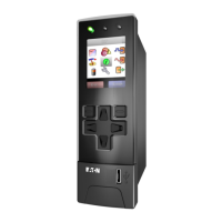
The S611 uses the User Interface Module (UI) to change the
configuration of operating parameters with a display to
indicate values and fault codes. By entering parameter
changes, parameter information is stored on the S611
printed circuit board. By default, the UI may be removed at
any time.
The S611 may be configured to fault if the user interface
module is removed for any reason.
Soft Starter
Frame
Sealed Inrush
Duration
(ms)VA Watts VA Watts
A 85 60 600 420 50
B 85 60 600 420 50
C 85 60 600 420 50
D 85 60 600 420 50
E 115 80 1200 840 50
F 115 80 1200 840 50
www.comoso.com

 Loading...


