34 S611 Soft Starter MN03902011E—May 2012 www.eaton.com
Printed Circuit Board (PCB) Removal
If necessary, mark all cables to aid in proper reattachment.
The PCB is marked with component identification
information adjacent to each connector base. See “PCB
Connector IDs” figure below.
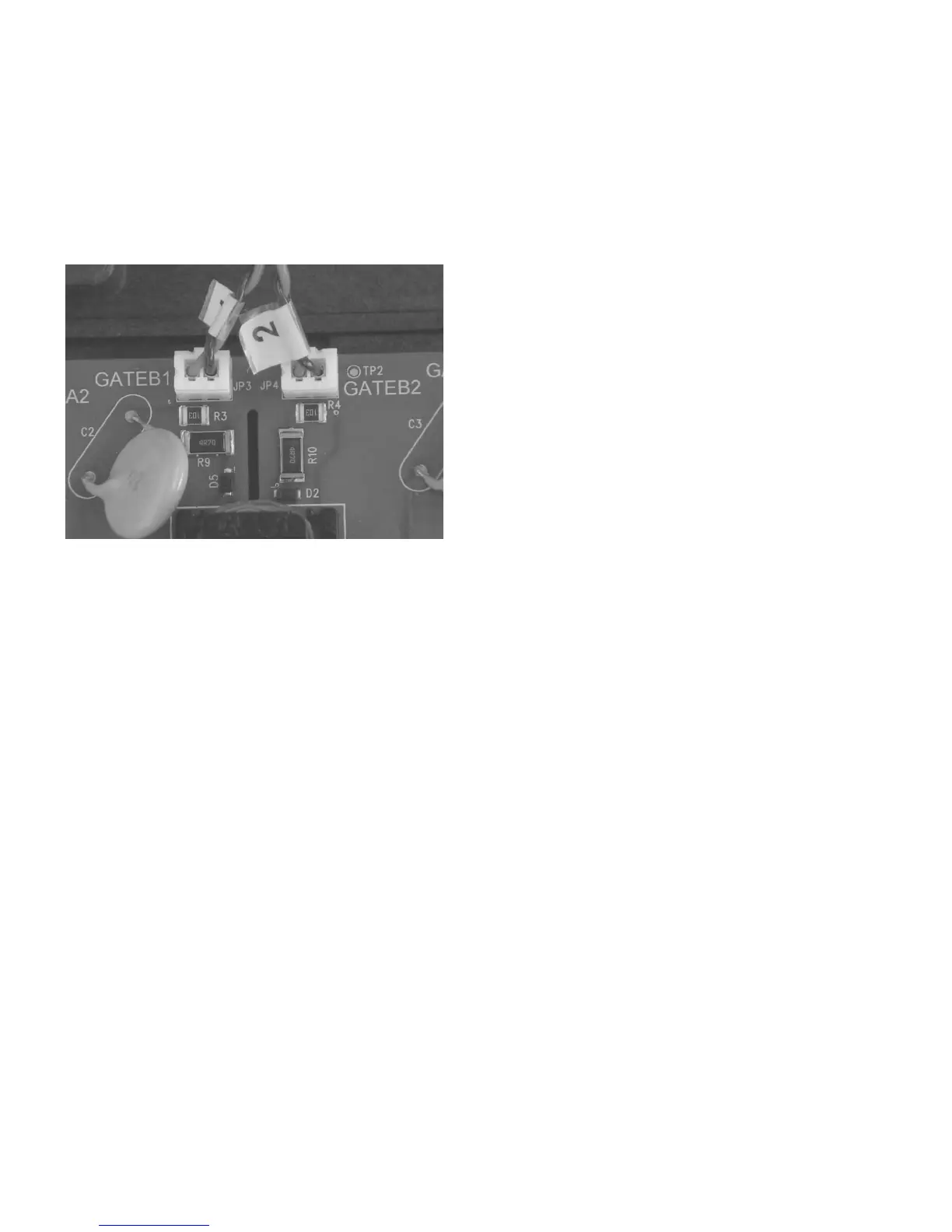
PCB Connector IDs
1. Disconnect leads from the PCB:
a) SCR gate leads—two per phase.
b) Temperature sensor leads—one per phase.
c) Current transformer leads— one per phase.
d) User Interface cable.
Note: All connectors except the User Interface cable use
detents to secure the connection. To remove, pull
each connector directly away from the PCB. Do not
twist or pry to remove connector from PCB. Do not
attempt to separate the connector by pulling on the
wires.
User Interface cable assembly locking tab is located
between connector and the cover. Use a small
screwdriver to depress locking tab. The cable may
also be removed after PCB is removed from the
cover.
2. Remove the 5 #1 Phillips self tapping screws—one in
each corner, one in center.
3. Remove PCB from cover assembly.
PCB Reinstallation
1. Place the PCB into position on the cover assembly.
2. Install all five screws by first turning the screw
counterclockwise until you feel the screw “drop” into
place. Torque to 8–10 lb-in.
3. Connect all leads, pressing firmly until you feel the
connector snap into place.
4. Reinstall cover assembly.
Cover Reinstallation
1. As the cover is placed onto the supports, carefully guide
wiring into place.
2. Ensure that the BYPASS VOLTAGE contactor connector
is properly connected prior to installing the cover
screws.
3. Install and torque all cover assembly screws to 22–27 lb-in.
4. Reinstall control wiring.
www.comoso.com

 Loading...