S611 Soft Starter MN03902011E—May 2012 www.eaton.com 43
User Interface Monitoring
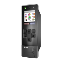
In the monitoring mode, the up-button ( ) and down-button ( ) are used to scroll through the
parameters that are available for display. When the end of the parameter list is reached (from
either direction), the next button press wraps to the beginning or end of the list. The following
table describes the operation of the monitoring mode.
Operation of the Monitoring Mode
Action Display Parameter Format (Example) LEDs ON
Default Average rms current x.xx if Avg <10
xx.x if Avg <100
xxx if Avg *100
Mode–Monitor
Units–A
Phase–AVG
Status–Ready
Down–( ) Phase A rms current x.xx if Ia <10
xx.x if Ia <100
xxx if Ia *100
Mode–Monitor
Units–A
Phase–IA | LI-L2
Status–Ready
Down–( ) Phase B rms current x.xx if Ib <10
xx.x if Ib <100
xxx if Ib *100
Mode–Monitor
Units–A
Phase–IB | L2-L3
Status–Ready
Down–( ) Phase C rms current x.xx if Ic <10
xx.x if Ic <100
xxx if Ic *100
Mode–Monitor
Units–A
Phase–IC | L3-L1
Status–Ready
Down–( ) Average rms voltage 480 Mode–Monitor
Units–V
Phase–AVG
Status–Ready
Down–( ) Phase A rms voltage 480 Mode–Monitor
Units–V
Phase–IA | LI-L2
Status–Ready
Down–( ) Phase B rms voltage 480 Mode–Monitor
Units–V
Phase–IB | L2-L3
Status–Ready
Down–( ) Phase C rms voltage 480 Mode–Monitor
Units –V
Phase–IC | L3-L1
Status–Ready
Down–( ) Total motor power X.XX if kW <10
XX.X if kW <100
XXX if kW *100
Mode–Monitor
Units–kW
Phase–AVG
Status–Ready
Down–( ) Motor thermal capacity/User
selected
0–100 Mode–Monitor
Units–TC
Phase–None
Status–Ready
www.comoso.com

 Loading...


