P.44
PM10U
EBARA
CORPORATION
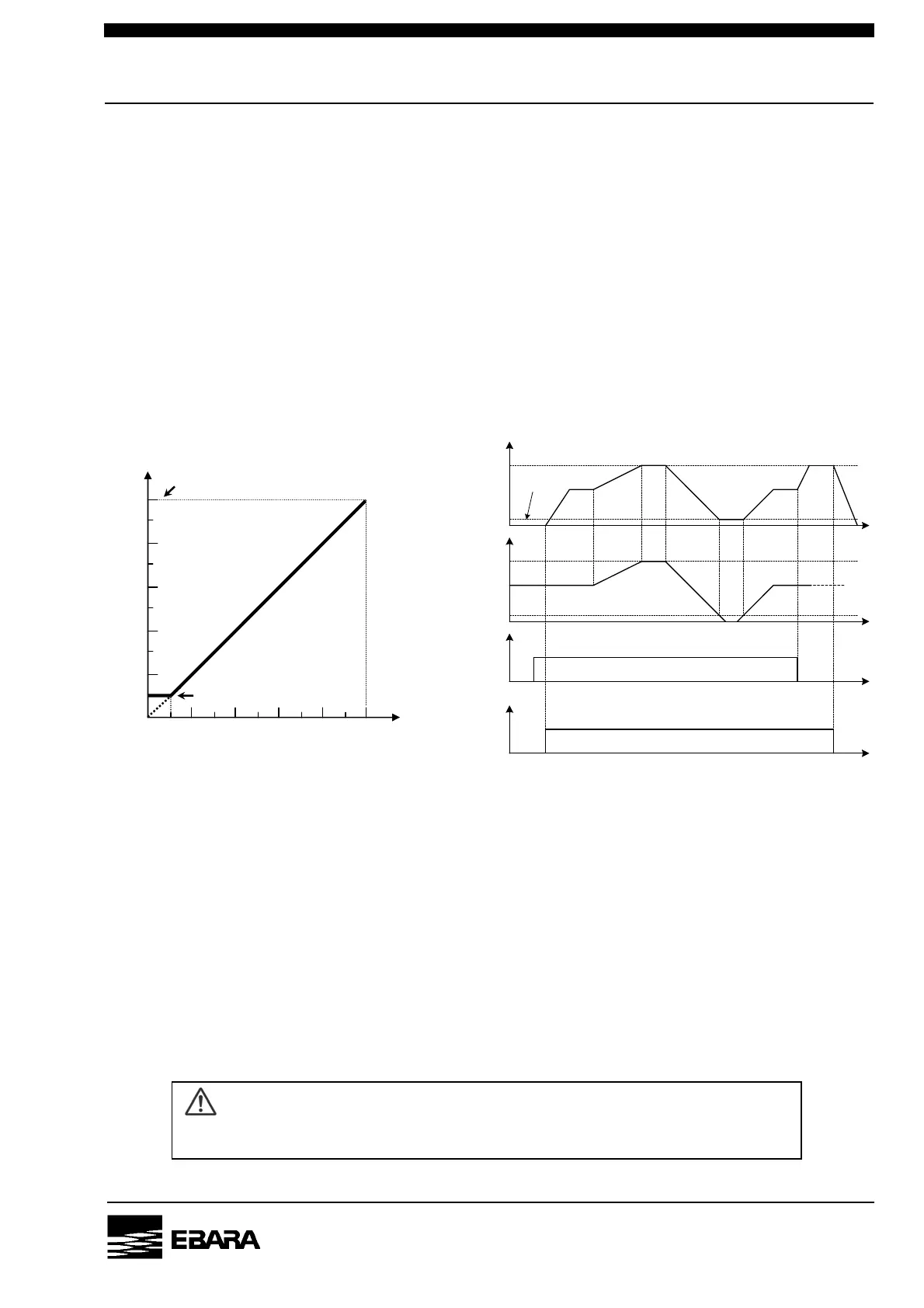
5.3 Pump speed control mode
The following is the pump operating procedures in “PUMP SPEED CONTROL MODE”.
1) Select “REMOTE MODE”. (See section 5.2)
2) Enable “PUMP SPEED CONTROL MODE” with closing Pin 4-12 of the control connector.
(See table 3.3)
3) Apply voltage (DC 0-10V) to Pin 7-15 of the control connector. (See table 3.3)
4) Run the pump with closing Pin 1-9 of the control connector. (See table 3.3)
5) The pump will start and the pump rotor will rotate at a rotational speed corresponding to the
applied voltage.
Fig.5.2 shows the relation between the applied voltage and the pump rotation speed.
Fig.5.3 shows the time chart of pump speed control.
[NOTE] “PUMP SPEED CONTROL MODE” is a feature available only in “REMOTE MODE”.
[NOTE] The pump rotation speed is directly proportional to the applied voltage between Pin 7-15.
[NOTE]If the applied voltage is less than 1V, the pump rotation speed maintain “0.1 x rated speed”.
[NOTE] The pump rotation speed can be changed even during the pump operation.
[NOTE] If you disable “PUMP SPEED CONTROL MODE” during the pump operation,
the pump rotation speed will be changed to the rated speed.
[NOTE] The pump will not start when an ALARM has been generated.
[NOTE] The control mode (REMOTE / LOCAL) can not be selected during RUN lamp is ON.
CAUTION
Do not apply voltage more than 10V. There is possibility that the pump to break down.
Run Signal
ON
Speed Control
OFF
ON
OFF
Input Voltage
10V
0V
Rotation Speed
6000min
-1
1V
600min
-1
0min
-1
Fig. 5.3 Time chart
Rated
speed
0.1 x Rated s
eed
Fig. 5.2 Applied voltage
Pum
rotation s
eed
Voltage [V]
Pump rotation speed [min
-1
]
0 1 10
0.1 x Rated speed
0
Rated speed