P.33
PM10U
EBARA
CORPORATION
3.3.2 Control Signal Wiring
Connect wires to the control connector for remote operation and remote monitoring.
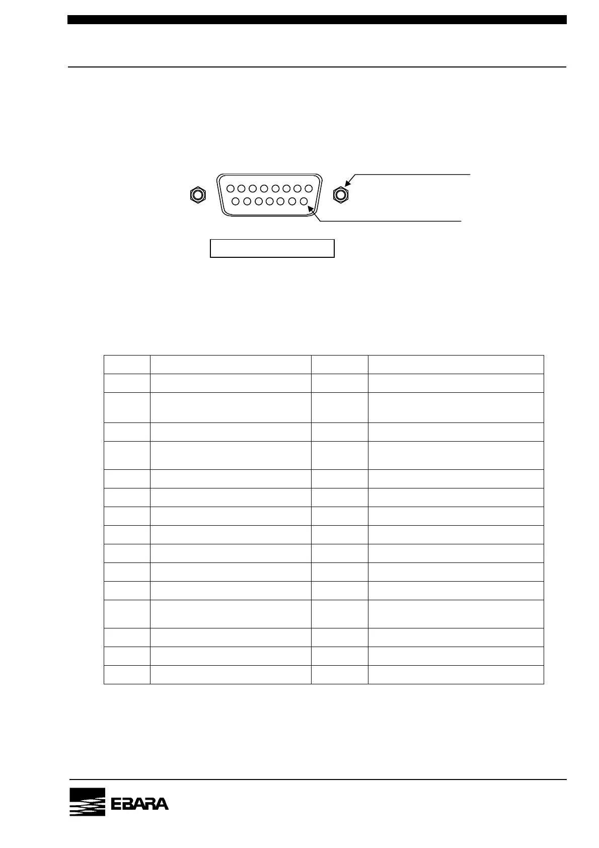
Fig.3.5, Table 3.4 and 3.5 show the pin assignment.
Table 3.4 Control Connector Pin Assignment
Pin. No. Signal name I/O Signal type
1 PUMP RUN (+) INPUT RUN : CLOSE
2 ALARM RESET (+) INPUT
RESET : CLOSE, Alternate
[note 1]
3 PUMP RUN/STOP STATUS (+) OUTPUT RUN : CLOSE
4
PUMP SPEED CONTROL
MODE (+)
INPUT CONTROL MODE : CLOSE [note 2]
5 ---
6 ALARM STATUS (+) OUTPUT ALARM : OPEN
7 PUMP SPEED CONTROL (+) INPUT DC 0-10 V [note 2]
8 ---
9 PUMP RUN (-) [note 3]
10 ALARM RESET (-) [note 3]
11 PUMP RUN/STOP STATUS (-)
12
PUMP SPEED CONTROL
MODE (-)
[note 3]
13 ---
14 ALARM STATUS (-)
15 PUMP SPEED CONTROL (-)
[note 1] RESET needs continuing signal over 5msec.
[note 2]
With Pin 4-12 close, the pump rotation speed is directly proportional to the applied
voltage between Pin 7-15. When 10V is applied, the pump rotation speed is maximum.
[note 3] 9, 10 and 12 pins are short-circuited by internal wiring.
Fig. 3.5 15 Pin D sub-Miniature Female Receptacle
(As seen from connecting side)
Screw lock size : M2.6
1 8
15 9
Connector pin surface : Au
Dsub-15pin Female