2-O&M_Startup_r1l Section 2Page 10
EBTRON, Inc • 1663 Hwy 701 S., Loris, SC 29569 • Toll Free: 800-2EBTRON (232-8766) • Fax: 843-756-1828 • EBTRON.com
The free area for -F fan inlet probes is the area calculated at the leading (upstream) edge of the
sensor housing where the probes are mounted (i.e. the probe blockage does not affect the area
calculation).
If factory default settings have not been changed in the field, the area parameter will match the area
printed on the hang tag of the sensor probes (exception: -F, -U and -B probe types).
Conversion of the velocity to volumetric airflow requires that the proper area of the measurement
location is used.
If the actual area is different, modify the area parameter and record the new size and area.
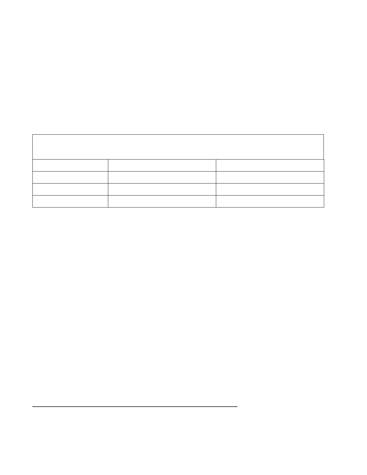
TABLE 2-1 QUICK AREA CALCULATIONS, sq ft [sq m]
W=Width, H=Height, D=Diameter
W, H and D are in inches [mm]
0.006944xWxH - 0.00149xHxH
0.000001xWxH - 0.0000002146xHxH
2.2.3. Transmitters with Analog Output Signals
Airflow measurement devices are typically used to determine the volumetric airflow rate in CFM [L/s]. The
following procedure assumes that the desired measurement at the B.A.S. is CFM [L/s].
2.2.3.1. ANALOG OUTPUT SIGNAL TYPE AND RANGE
Verify the following:
Verify that the analog input configuration of the B.A.S. matches the output configuration of the
transmitter.
The AOUT parameter firmware setting can be viewed/modified using the shortcut sequences below
or through the Settings Menu. See Section 3 for more information.
Simultaneously press the ESC and ↑ pushbuttons during normal operation to quickly verify the setting
for AOUT. Some models have an additional prompt to instruct the user to modify jumpers and/or
switches on the circuit board or option card.
Use the output test tool provided in the TOOLS menu to set a fixed output signal to verify that each of
analog output signal is converted properly by the B.A.S. See Section 4 for more information.
Failure to properly configure the output signal will result in significant measurement error at the B.A.S.
2.2.3.1.1. Advantage IV Gold Series Models (Except GTx116e and GTx108e)
The output is set by switches SW1 and SW2 on the output card provided with the transmitter for voltage
(VDC) or current (mA). If a switch is set for voltage, only the corresponding voltage options of 0-5V or 0-10V
will be available. If a switch is set for current, only 4-20mA will be available.

 Loading...