IGNITION SYSTEM
CS-2511TES
251Ts, 251TCs
17
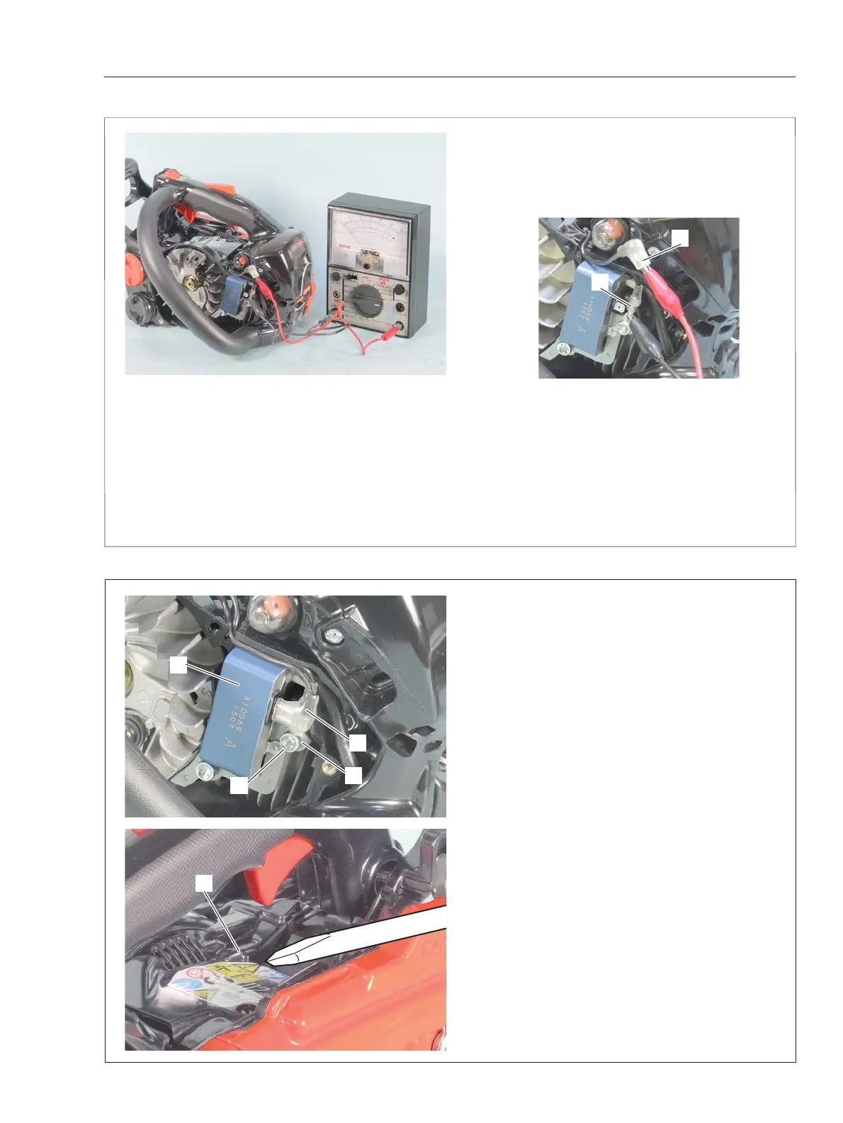
3-5 Inspectingignitionswitch
1. Remove starter assembly from unit.
2. Connect one probe of Ohm-meter or multi-meter
to ignition switch terminal (A). Connect the other
probe to another ignition switch terminal (B).
3. When ignition switch is “RUN” position, tester
should indicate innite resistance.
4. When ignition switch is in “STOP” position, tes-
ter should show that the circuit is in conducting
state (closed circuit).
5. If ignition switch is defective, replace with a new
one.
B
A
E
C
D
B
3-6 Replacingignitionswitch
{Removing}
1. Remove starter assembly from unit.
2. Remove bolt (A), ignition switch terminal (B) and
(C) from ignition coil (D).
3. Insert screwdriver or equivalent between dust
cover (E) and engine cover, and pry dust cover (E)
away from engine cover.
A