Section 6. Ice Protection Eclipse 5OO Systems Manual
Copyright © — Eclipse Aviation Corporation
98 Version 2.0 April 2007
6.4.2 Ice Protection Synoptic
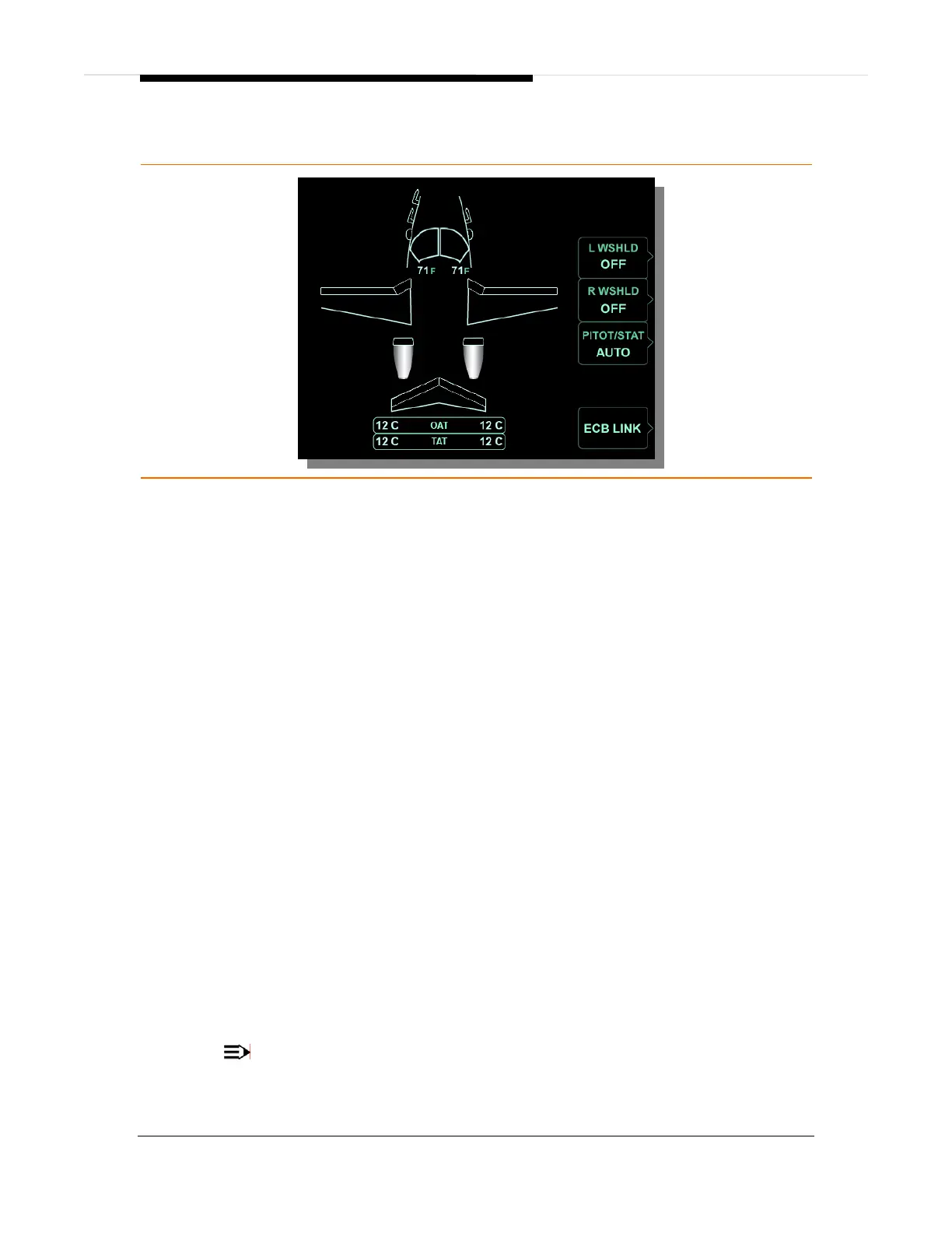
Figure 64. Ice Protection Synoptic
L and R WSHLD LINE SELECT KEY
ON .............................................................................................Windshield heat on
OFF............................................................................................ Windshield heat off
WINDSHIELD DISPLAY
Green outline .............................................................................Windshield heat on
White outline.............................................................................. Windshield heat off
Amber outline ...........................................................Windshield overheat or failure
White temperature ......................................................... Normal temperature range
Red temperature.............................................................Overheat (with red OVHT)
PITOT/STAT LINE SELECT KEY
ON ..............................................................................................Pitot/static heat on
AUTO........................................................................................................Automatic
PROBE DISPLAY
Green....................................................................................... Probe/Static heat on
Amber ................................................................................. Probe/Static heat failed
DE-ICE BOOT DISPLAY
Green............................................................................................De-ice system on
White.............................................................................................De-ice system off
Amber ...................................................................................... De-ice system failed
Engine Display
Green...........................................................................................Engine anti-ice on
White............................................................................................Engine anti-ice off
Amber ..................................................................................... Engine anti-ice failed
OAT ..........................................................................................Outside Air Temperature
TAT ............................................................................................... Total Air Temperature
NOTE:
Amber and red display colors are consistent with CAS message colors.