Section 4. Landing Gear and Brakes Eclipse 5OO Systems Manual
Copyright © — Eclipse Aviation Corporation
54 Version 2.0 April 2007
4.2 Aircraft Computer Systems (ACS) Interfaces
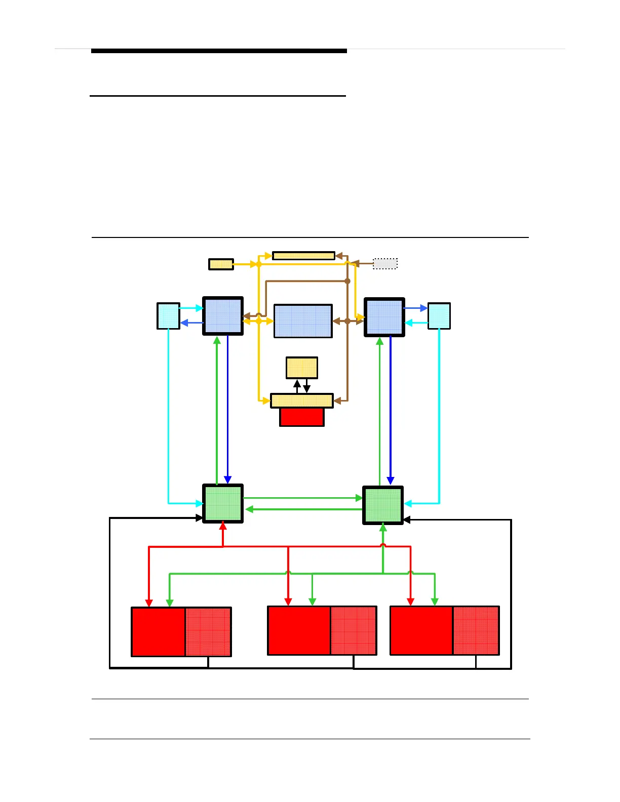
The flight crew can retract or extend the landing gear using the landing gear switch
on the center switch panel. Pilot commands from the landing gear switch are sent
through the PFD to both ACS’ which in turn command the three independent landing
gear actuators. Commands for gear position go directly to the actuator motor and
individual actuator status is sent back to the ACS. There are also several
independent position indications from several proximity sensors that are also sent to
the ACS for status display on the MFD.
Emergency extension of the landing gear is a direct mechanical release and does not
require ACS control to accomplish. There is a emergency landing gear handle
proximity switch that is monitored by the ACS that reports if the emergency gear
handle remains extended following an emergency gear extension.
Center Switch Panel
Right
PFD
Left
ISS
Left
ACS
L KBD
Autopilot Control Panel
Left
PFD
Optional
R KBD
MFD
Right
ISS
Engine
Start
Switches
ACS-PFD Communications Bus
Left Byteflight Bus
Right Byteflight Bus
ACS-PFD Communications Bus
Landing Gear
Switch
Nose Landing
Gear Actuator
Left Main
Landing Gear
Actuator
Left ACS Communications Bus
Position Information to ACS
Right
ACS
Right Main
Gear Actuator
Position
Indications
Position
Indications
Position
Indications
Right ACS Communications Bus
Figure 37. Landing Gear-ACS Interface