Section 8. Engines & Fire Protection Eclipse 5OO Systems Manual
Copyright © — Eclipse Aviation Corporation
154 Version 2.0 April 2007
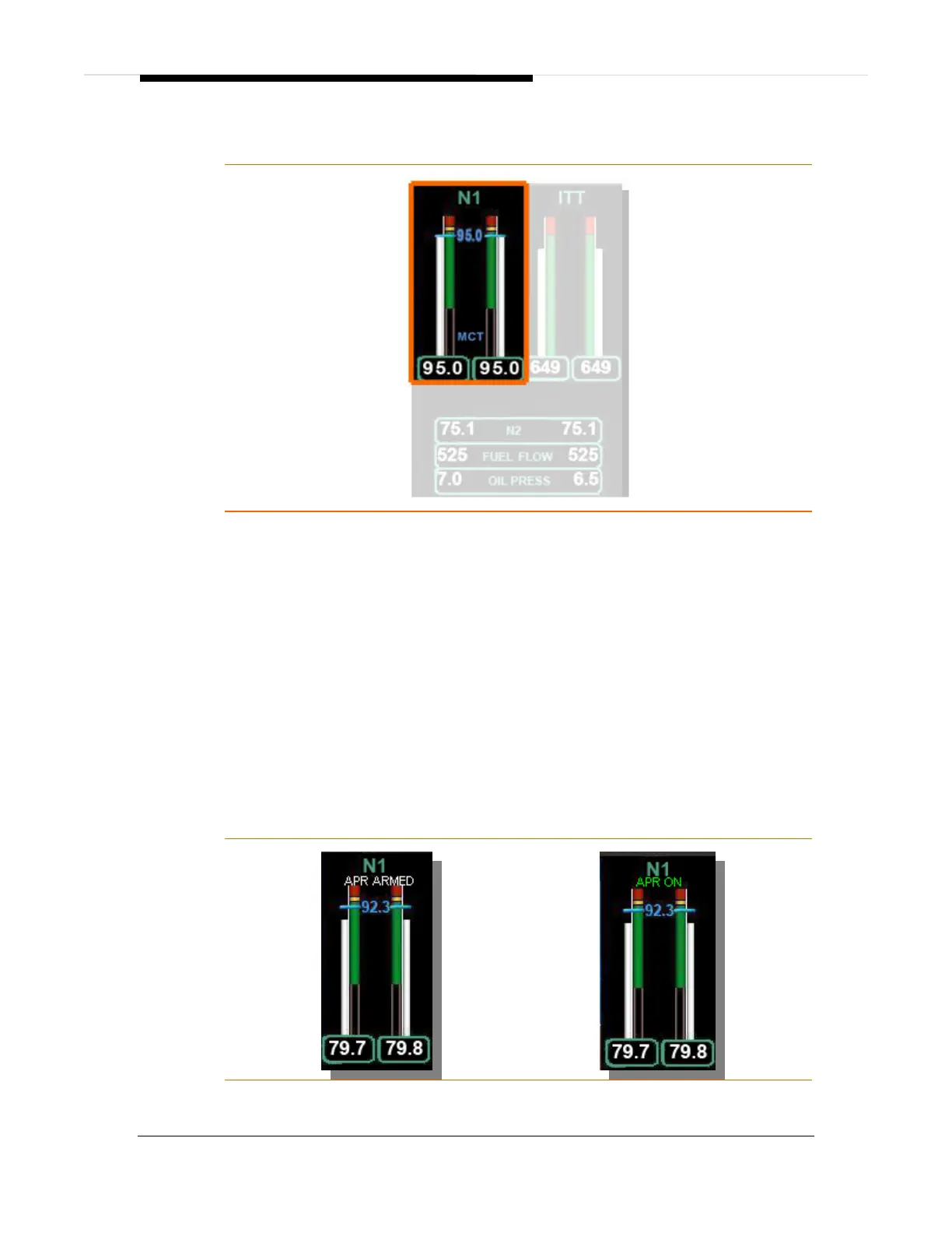
8.4.7 N1 RPM
Figure 97. N1 Tape
N
1
is continuously displayed on the MFD with a moving tape and digital readout in
percent of maximum RPM. The scale of the tape is 0 to 105%. An adjacent tape
displays N
1
limits. A green band on the limit tape extends from approximately 21% to
100%. An amber band extends from 100% to 101%. A red band begins at the
maximum continuous limit of 101%.
The digital value and moving tape are white for N
1
values in the green band, in amber
for N
1
values in the amber band, and in red for N
1
values above the RPM limit. If the
RPM exceeds the limit for 20 seconds, a L (R) ENG EXCEEDANCE warning
message appears.
A blue bug and blue digital readout between the left and right N
1
tapes display the N
1
target calculated by the ACS for the mode of flight.
With the throttles advanced to the takeoff setting the state of the APR is displayed
above the N
1
tapes as either APR ARMED (white) or APR ON (green).
Figure 98. APR Indications