Section 10. Electrical Eclipse 5OO Systems Manual
Copyright © — Eclipse Aviation Corporation
230 Version 2.0 April 2007
MECHANICAL CIRCUIT BREAKERS
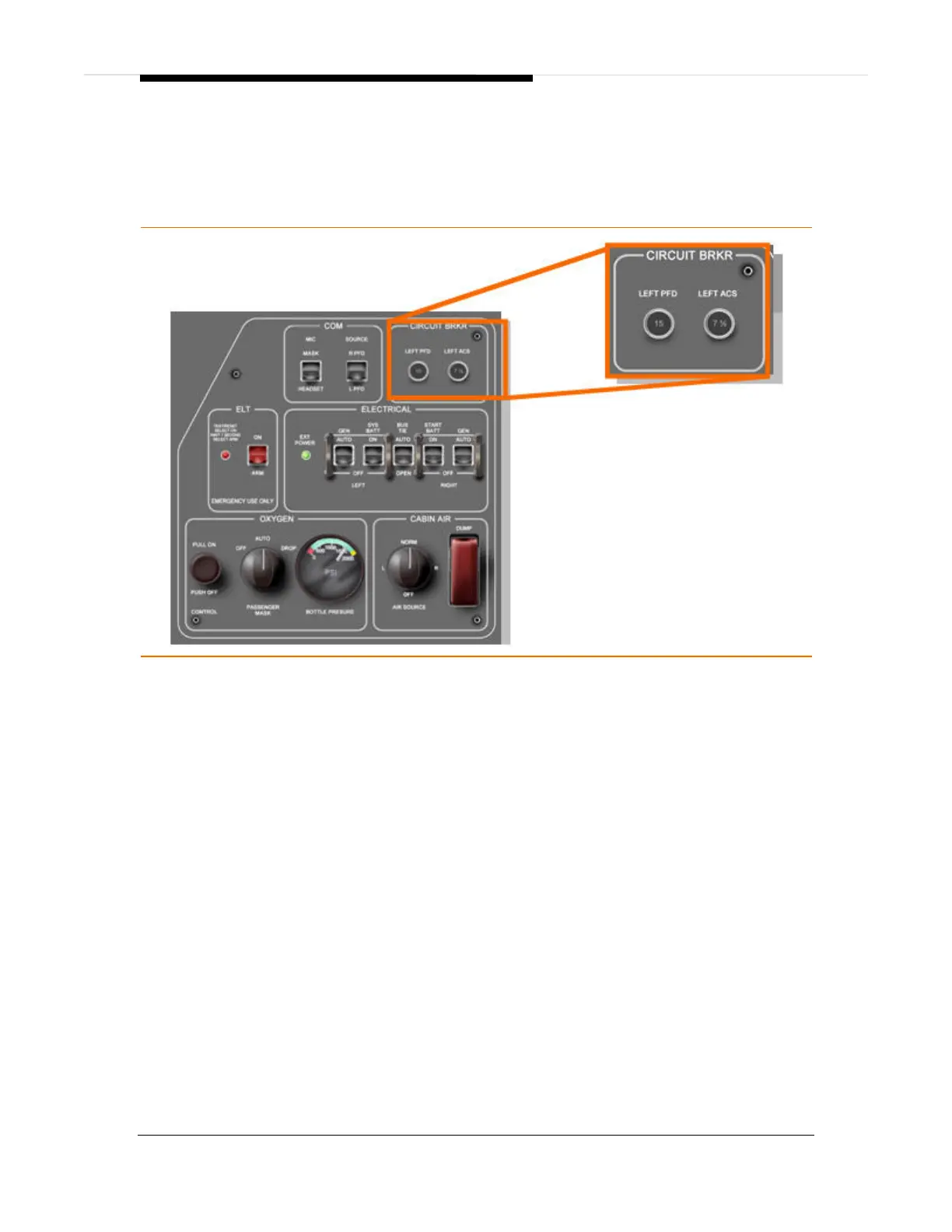
There are two mechanical circuit breakers on the left switch panel that supply power
to the left PFD and left ACS. This ensures that electrical power can be restored to
the critical flight instruments and ACS if an event causes all the ECBs to turn off.
Figure 143. Mechanical Circuit Breaker Location
ELECTRONIC CIRCUIT BREAKERS
Power is distributed to the various electrical components through ECBs rather than
mechanical circuit breakers. Each ECB detects over-current conditions to trip the
ECB to protect the aircraft wiring.
127 ECBs are contained in five Electronic Circuit Breaker Units (ECBUs), each
associated with one electrical bus:
ECBU #1 Left Forward Bus
ECBU #2 Right Forward Bus
ECBU #3 Battery Bus
ECBU #4 Left Aft Bus
ECBU #5 Right Aft Bus
The ECBs can be monitored and controlled and on the ECB Synoptic page on the
MFD. Each ECB has five possible states:
AUTO/ON Normal state
AUTO/OFF ECB turned off by the ACS
TRIPPED ECB off due to circuit fault
PULLED ECB opened by the pilot
COLLARED ECB locked out by a maintenance technician