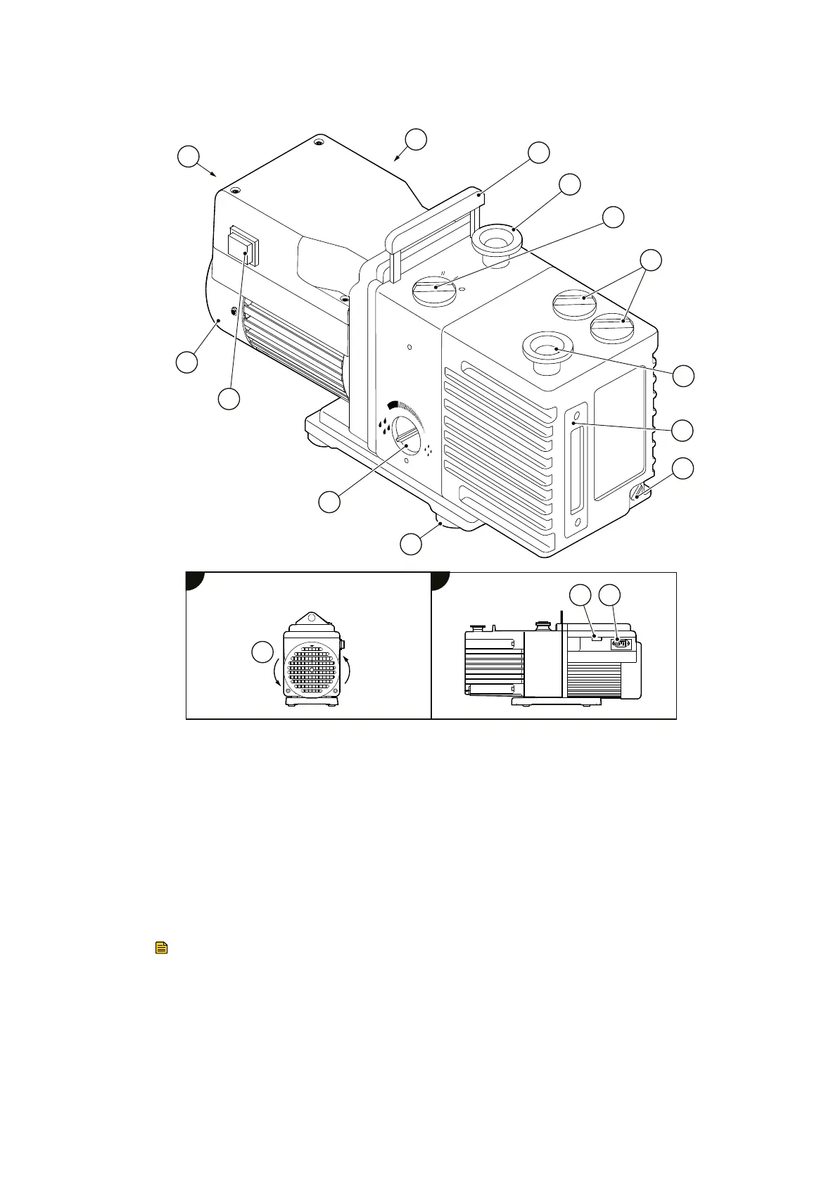
Figure 1 The RV pump
1
2
3
4
5
6
7
8
9
10
11
12
CS/1104/A
A
B
A
B
14
13
1. Liing handle* 2. NW25 inlet‑port
3. Gas‑ballast control 4. Oil ller‑plug
5. NW25 outlet‑port 6. Oil‑level sight‑glass
7. Oil drain‑plug 8. Rubber feet (4 o)
9. Mode selector 10. On‑o switch†
11. Motor fan‑cover 12. Correct direcon of rotaon
13. Voltage indicator 14. Electrical inlet‑connector
1. Liing handle* 2. NW25 inlet‑port
3. Gas‑ballast control 4. Oil ller‑plug
5. NW25 outlet‑port 6. Oil‑level sight‑glass
7. Oil drain‑plug 8. Rubber feet (4 o)
9. Mode selector 10. On‑o switch†
11. Motor fan‑cover 12. Correct direcon of rotaon
13. Voltage indicator 14. Electrical inlet‑connector
* RV3 and RV5 pumps only, a liing bracket is ed to RV8 and RV12 pumps.
† Single
‑
phase pumps only.
Note:
Single
‑
phase RV3/RV5 pump shown.
2.3 Descripon
The RV rotary vane pump is shown in Figure: The RV pump. Refer to Figure: The RV pump
for item numbers in brackets in the following descripons. The RV pumps are two‑stage,
03/2021 - ©Edwards Limited
Page 10A65201880_AA
A65201880_AA - Introducon
 Loading...