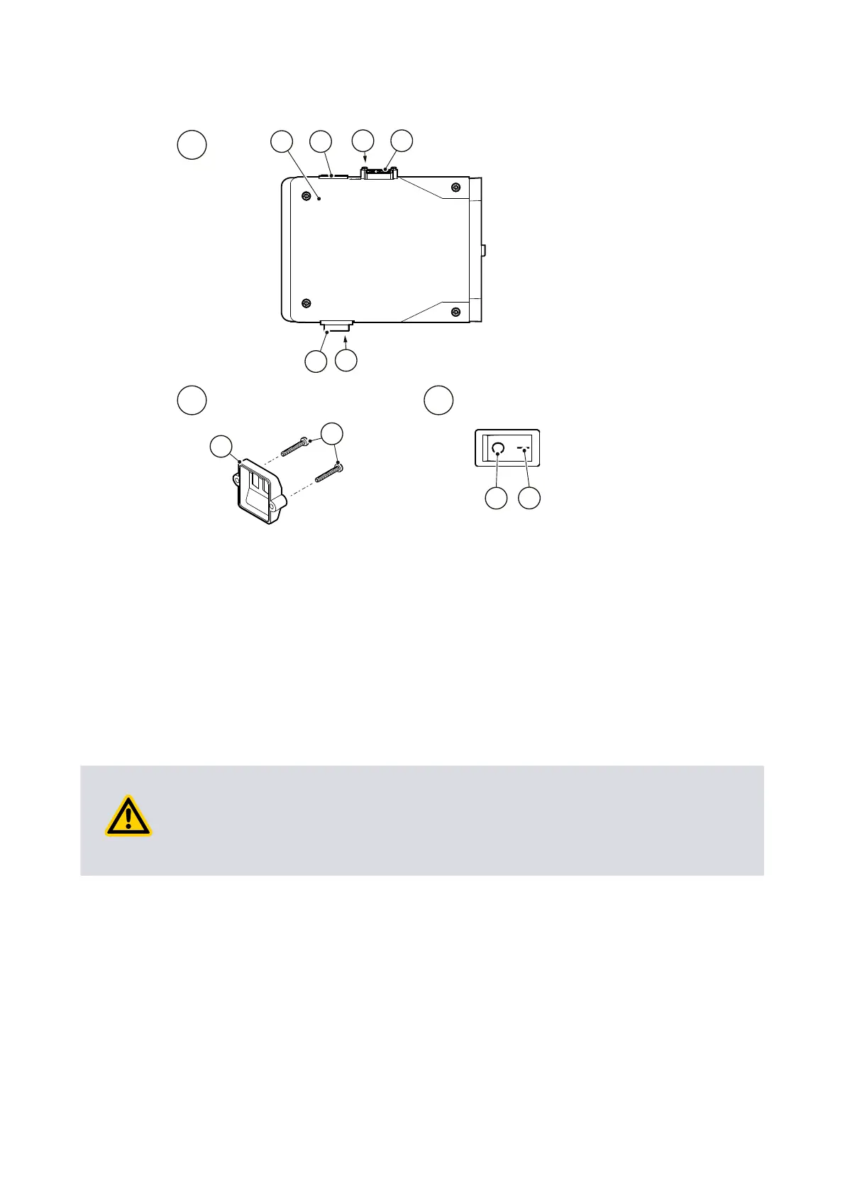
Figure 4 Motor voltage conguraon: single-phase pumps
A. Top view of motor B. View of voltage selector switch cover
C. View of On-o switch
A. Top view of motor B. View of voltage selector switch cover
C. View of On-o switch
1. Terminal box 2. Electrical inlet-connector
3. Voltage selector switch 4. On-o switch
5. Voltage selector switch cover 6. Retaining screws
7. Posion 'I' (on) 8. Posion '0' (o)
1. Terminal box 2. Electrical inlet-connector
3. Voltage selector switch 4. On-o switch
5. Voltage selector switch cover 6. Retaining screws
7. Posion 'I' (on) 8. Posion '0' (o)
4.7 Electrical installaon: three-phase pumps
4.7.1 Check and congure the motor
CAUTION:
Ensure that the motor is correctly congured for the local electrical supply. If the
pump is operated when the motor is not correctly congured for the electrical supply,
the motor will be damaged.
1.
Remove the screws which secure the cover of the motor terminal-box. Remove the
cover.
2.
Remove the cable-gland from the inside of the terminal-box and t the cable-gland
to the cable lead through hole in the side of the terminal-box.
3.
Ensure that the motor is correctly congured for the local electrical supply. If
necessary, recongure the links (Figure: Three-phase electrical connecons: 200–
03/2021 - ©Edwards Limited
Page 29A65201880_AA
A65201880_AA - Installaon

 Loading...