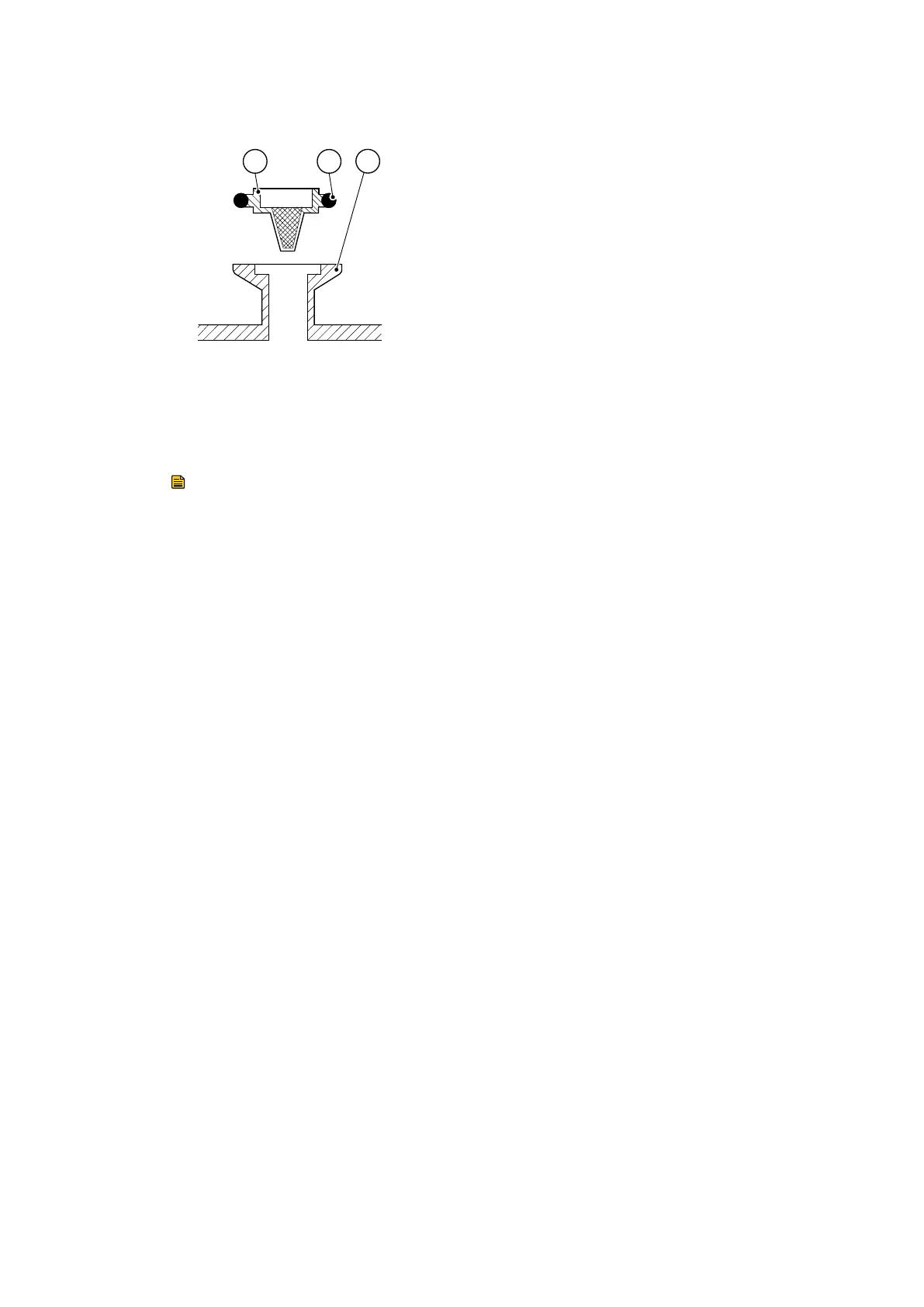
Figure 7 Inlet-lter assembly
1. Centring-ring and lter assembly 2. O-ring
3. Inlet-port
1. Centring-ring and lter assembly 2. O-ring
3. Inlet-port
6.6 Inspect and clean the gas-ballast control
Note:
The gas-ballast lter element (Figure:Gas-ballast control assembly, item 7) is retained in
its seang with adhesive; do not try to remove it.
1.
Refer to Figure:Gas-ballast control assembly. Turn the gas-ballast control (1) to the
high ow posion (posion ‘II’).
2. Push the control down against the compression spring (6) as far as it will go, then
turn the control anclockwise slightly to release the bayonet-lugs (5) and remove
the control.
3. If necessary, wipe the control with a clean, dry, lint-free cloth and check that the
air-hole (3) is not blocked.
4. Ret the control into the gas-ballast inlet and ensure that the compression spring
locates correctly between the bayonet-lugs.
5.
Push the control down as far as it will go and turn the control clockwise slightly
unl the bayonet-lugs engage correctly.
6. Reset the gas-ballast control to the required posion.
03/2021 - ©Edwards Limited
Page 43A65201880_AA
A65201880_AA - Maintenance

 Loading...