STP-301/451 Series Instruction Manual
13-8
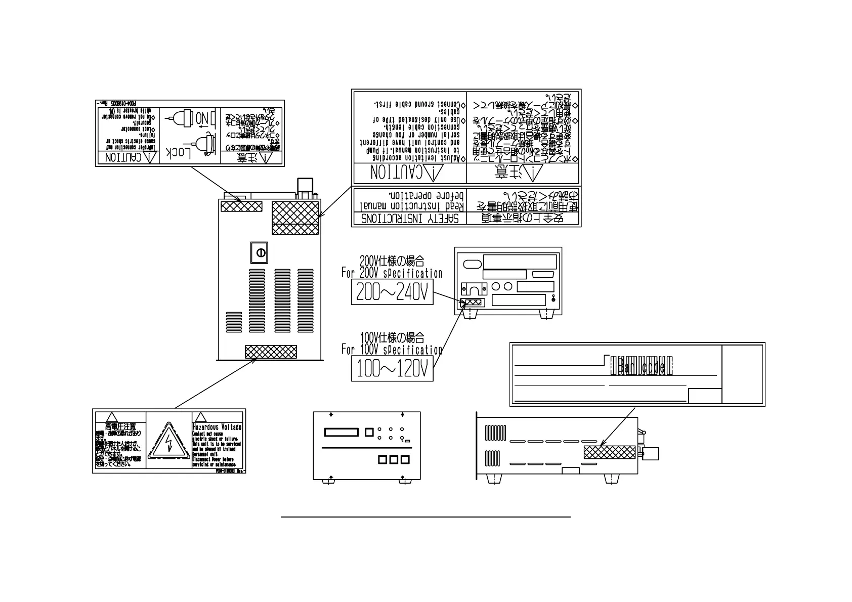
注意
!
CAUTION
!
Turbomorecular pump Control Unit
SERIAL No.:
MODEL: SCU-
MANUFACTURING DATE:
WEIGHT: kg
MANUFACTURED BY: Edwards Japan Limited.
1078-1, Yoshihashi, Yachiyo-shi, Chiba, Japan
CE
Figure 13.5 Label Affixing Positions for the STP Control Unit