STP-301/451 Series Instruction Manual
8-7
Operation
8.3 CON4 Connector (Optional accessory)
This is a connector for remote input/output signals.
This connector can maintain compatibility with the remote I/O signal of the STP-200/300/400
series.
The remote input signal from the CON 4 connector is valid by setting No.4 switch of the
DSW-B on the top panel to "ON". In this case, remote input from I/O TB2 terminal is invalid.
(Refer to Figure 6.3, "STP Control Unit Top Panel" for the position of "DSW-B".)
This connector is GP-IB
*1
type (24pin)
8.3.1 Remote Input Signals
Use input signals according to Table 8.5 and Figure 8.3. See Section 7.6, "Remote Operation
(CON4)".
This input signal is valid only when No.4 of the DSW-B is "ON" in the remote operation.
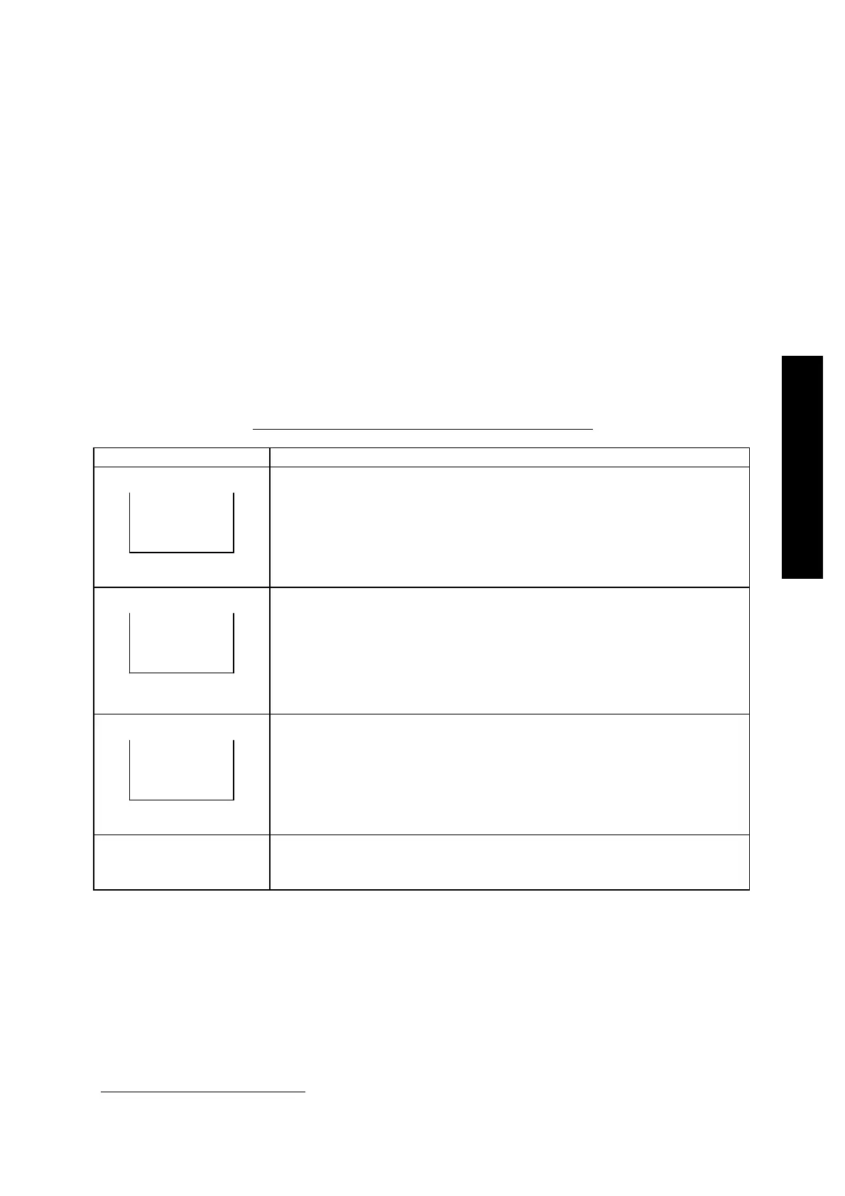
Table 8.5 CON4 Connector (Remote Input Signal)
Pin Description
(2) (14)
RESET IN
+ -
Pins for inputting the RESET signal.
When inputting 24VDC between (2)-(14) for 0.3 seconds or more,
the "FAILURE" lamp is turned off.
Connect the (+) side to (2), and the (-) side to (14).
(It is an equivalent to the pin for inputting the "POWER OFF"
signal of the STP-200/300/400 series.)
(3) (15)
START IN
+ -
Pins for inputting the START signal.
When inputting 24VDC between (3)-(15) for 0.3 seconds or more,
the pump starts operation.
However, when inputting the signal simultaneously with switching
"ON" the breaker on the rear panel, continue to short the circuit
for 5 seconds or more.
Connect the (+) side to (3), and the (-) side to (15).
(4) (16)
STOP IN
+ -
Pins for inputting the STOP signal.
This STOP signal has priority over he START signal.
When inputting 24VDC between (4)-(16) for 0.3 seconds or more,
the pump stops operation.
Connect the (+) side to (4), and the (-) side to (16).
(1) (13)
Not used.
(It corresponds to the pin for inputting the "POWER ON" signal of
the STP-200/300/400 series.)
*1
: General Purpose - Interface Bus (Conforms to IEEE-STD-488-1978)