STP-301/451 Series Instruction Manual
4-9
Installation
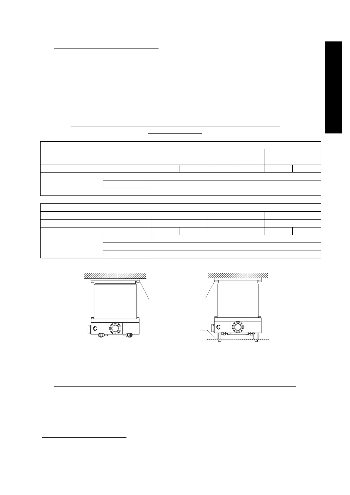
1) When securing the inlet port with bolts
Refer to Table 4.2 for torque in pump abnormality and recommended securing bolts.
Secure the inlet port flange with all of the boltholes of the size specified in the Inlet
Port Flange Standard.
Secure the base with all 8 screw-holes for legs or all 8 attached legs.
Follow "CAUTION" on page 4-8 about legs and bolts for securing the base. Make
sure that the recommended securing bolt may be different depending on the method
of securing the base.
Table 4.2 Maximum Torque predicted and Recommended securing bolt
for inlet port flange
Model of TMP STP-301
Type of flange VG100 ISO100F
*1
ICF152
Torque in pump abnormality [Nm] 3.8×10
3
3.8×10
3
3.8×10
3
Base(8 positions)securing No Yes No Yes No Yes
Type of bolt Standard
Type of steel
*2
Stainless steel
Recommended
securing bolt for TMP
Flange
Strength
*2
70 or more
Model of TMP STP-451
Type of flange VG150 ISO160F
*1
ICF203
Torque in pump abnormality [Nm] 3.8×10
3
3.8×10
3
3.8×10
3
Base(8 positions)securing No Yes No Yes No Yes
Type of bolt Standard
Type of steel
*2
Stainless steel
Recommended
securing bolt for TMP
Flange
Strength
*2
70 or more
(a) When the base is not secured (b) When the base is secured
Figure 4.5 Example of securing the STP Pump (When securing the inlet port with bolts)
*1
Maximum predicted torque of ISO flange type pump is the same as that of ISO_F flange type pump.
*2
Refer to ISO898-1 (JISB1051), ISO3506 (JISB1054) and AMS6419 (Aerospace Material Specification)
Recommended
fitting bolt for flange
Secure the base